
The above section of code will create all the appropriate blocks to output anumber out port 0 (lines 0-5) of the daq card. In this example the card is located as device 8. In most applications you would use a control to select this rather than a constant, as was done here.
The blocks in use are a DAQmx Create Virtual Channel, DAQmx Start Task, DAQmx Write, DAQmx Stop Task and DAQmx Clear Task
Notice that the write function is a polymorphic block that has been seleected as an n channel, 1 sample with data as an array of unsgned 8 bit integers. There are a variety of options on the output data format, but for this example I have chosen a simple number scheme. If you are trying to deal with single bits, you may want to select the boolean array options.
The left most block creates a task using "DEV4" lines 0 through 6 as digital outputs. In this case Dev8 is the myDAQ connected to the machine that I created these snippets from. The next block to the right starts this task. It is sequentially executed following the create task because the task output and error output of the create task are wired to its inputs. These functions need to be done to "define and start" what I/O fucntion is going to happen and how.
Up top in the middle is the data to be written. A 1-Dimensional (1-D) array is built directly from a single integer. This results in a binary representation. (1 becomes [000001] and 5 becomes [000101], etc.)
The third block is the actual output. If you are exectuing in a loop, this is the block that must reside inside the loop. This DAQmx write block will take a 1-D array of 8 bit words, containing a single element (not more) and send it to the physical lines that were defined in the create task. If this vi were definded as an N sample, the array could contain multiple elements. This block could send other things besides numbers, such as boolean values in an array. It is purly based on how it is configured.
The last two blocks on the right are a stop and erease task. These must reside outside the loop and release the resourses that the create task has taken control of.
If you run this snippet with the hardware setup for the dice game, you will see that the 6 bits of the led display in the schematic can represent values from 0 to 63.

basic digital output boolean write.png
If you would rather work directly with bits, the above snippet shows one method. Three things have changed from the previous snippet: the line grouping property on the Create Virtual Channel block, the array of data to be written, and the settings on the DAQmx Write block. The array of data is now made up of multiple boolean values, instead of one numeric value.
In order for the Write block to interpret the array properly, the settings have been changed to match the new input: a 1-D boolean array. If the Write block's settings do not match its input, the program will not run. Similarly, if the line grouping is not changed to "one channel for each line" the program will return the following error:
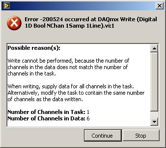
If this snippet is run with the hardware setup for the dice game, you will see that each of the 6 bits of the led display represent one of the boolean T/F constants.
It is often advantagous to deal with things as arrays, rather than as numbers. The following snippet shows how to convert an unsigned integer into an array of boolean values. This snippet utilizes a case structure that has a case statement for each possible value of the numeric. Each of these cases contain a series of boolan constants that are build into an array and passed to the array output. This allows the array to contain any combination of true/false values for any of the numbers. If the number comming into the case does not have an associated case frame, then the "default" frame is utilized.
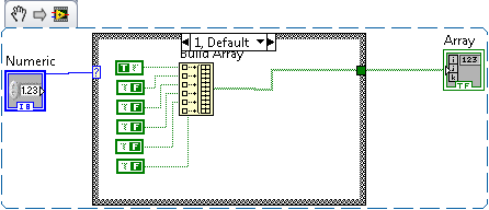
Convert number to binary array.png
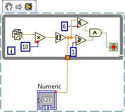
Labviw has a built in random number generator, however the generator only creates a random number between 0 and 1. For this program you need a random number between 1 and 6, inclusive. This code snippet shows one way to do this.
The loop runs until it is true that the random number x 10 is greater than or equal to 1 and less than or equal to 6. Both conditions must be true. If either are false, the system generates a new random number and tests the new number.
This is done by multiplying the result of the random function by 10, and then rounding to the closest integer value. The two greater than and less than checks make sure the ruslts fall within the required range. If not, the loop is not terminated and will genearte another number.
Often it is important to wait for an event or operator input. This small code chunk will wait for a button to be pressed and then allow the count to be incremented.
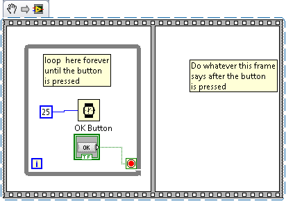
The sequence requires that the ok button loop complete before it will proceed to the next frame in the sequence. The first frame will start the while loop containing the button. This loop processes every 25ms. This wait funtion is inserted to prevent the program from bogging down the processor on slower computers. This loop will continue to execute until the button is pressed, turning the stop terminal on. With the while loop done, the sequence will move to teh second frame. This second frame will contain whatever instructions you want the program to do after you press the button. It is often advantagous to put this entire structure inside another while loop to keep the program running infinitely.