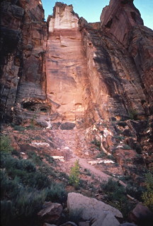
I also focused on unraveling the genesis of secondary jointing
in the massive Navajo Sandstone, which reaches a thickness of 2300
feet around Zion National Park in southwestern Utah. This view
shows one set of the near-vertical regional systematic joints which
pervade the entire unit, exposed in the Short Creek drainage of northern
Arizona.
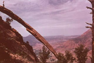
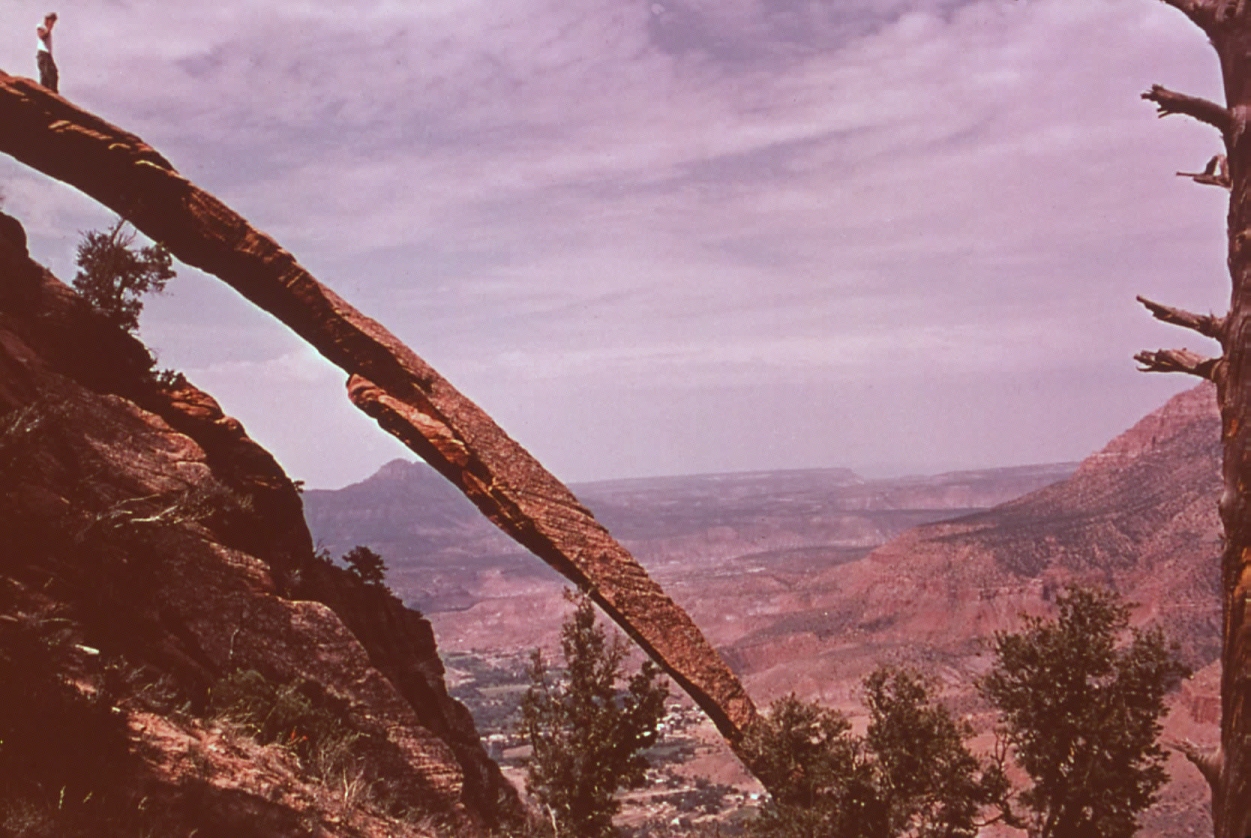
The Navajo Sandstone in Zion Park contains some prolific examples
of sheet joints in sedimentary rock. This view shows a isolated
sheet joint developed in the upper Navajo, about 2300 feet above the
floor the North Fork of the Virgin River, overlooking Park Headquarters.
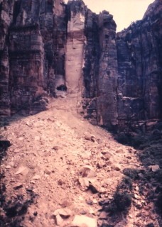
In April 1958 a massive rockfall occurred at Gallery 3 along the south
side of Pine Canyon, closing the Zion-Mt. Carmel Tunnel (Utah Route
9). About 85,000 tons of Navajo Sandstone separated from the
cliff and tumbled down, more or less disintegrating on impact.
Shannon & Wilson of Seattle, WA was engaged by the Park Service
to study support problems in the Zion-Mount Carmel Tunnel in 1979-80.
They retained my services as a consultant to help them with the project
and provided me with samples and opportunities for exploration and
mapping of the troubled cliffs along the 1.3 mile long tunnel.
This is what the Gallery 3 failure area looked like when I carried
out my studies during the fall of 1979.
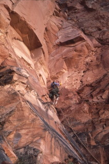
Here I am hanging off the cliff in the Gallery 3 failure area, photographing
exposed concrete tunnel lining. I found as little as 12 inches
of cover between the tunnel lining and the cliff face, causing distress
to the tunnel lining! Notice the open feather fractures above
me! I was thrilled to be paid for such work!
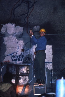
During the course of my studies, we drilled around each of the tunnel’s
six ventilation openings, with additional emphasis on Gallery 3, where
the greatest problems existed. Here I am placing an inflatable
impression packer in an NX hole we had previously drilled with a triple
tube core barrel to obtain samples. We were surprised at the
degree of secondary fracturing exhibited in the rock.
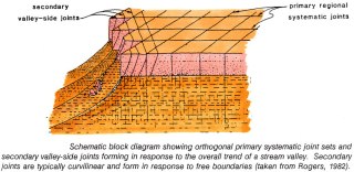
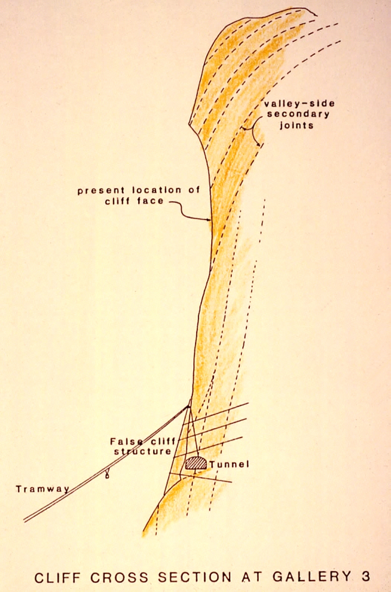
This is a sketch I made of the curvilinear secondary joints responsible
for the spectacular rock slides in the Pine Canyon area of Zion Park.
These valley-side joints form in response to the geologic excavation
of the canyon, cutting across the regional systemic joint suites.
Both types of joints exert great influence on slope morphology and
failure mechanisms.

This sketch shows the recommended method of repairing the Gallery
3 distress, using prestressed rock tendons and died concrete.
The entire repair operation would be air-lifted to the cliff face
using a tramway high line, to avoid disturbing the slopes. Years
later a similar scheme I devised for repairing Telegraph Hill in San
Francisco won an innovative design award from the American Public
Works Association.

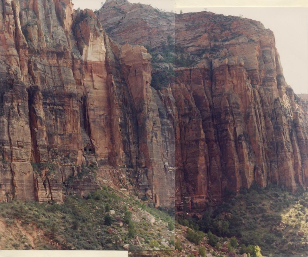
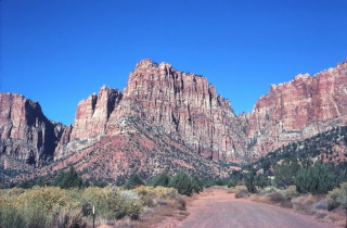
This view shows the cliff face in Pine Canyon adjacent to the Gallery
3 rockfall area. Each of the joint-bordered “columns”
exhibits a distinctive form that provides clues about the mechanisms
by which the cliff face retreats. Rock Columns I thru V are
separated by clusters of near-vertical regional systematic joints,
spaced about 80 feet apart.
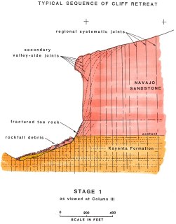
Stage 1 depicts the present situation at Column III, where the
Tunnel Gallery 3 rockfall occurred in April 1958. Note the positions
of near-vertical primary systematic joints and curvilinear secondary
joints, formed in response to the excavation of Pine Canyon.
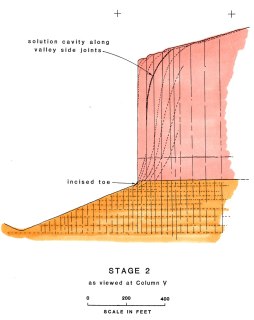
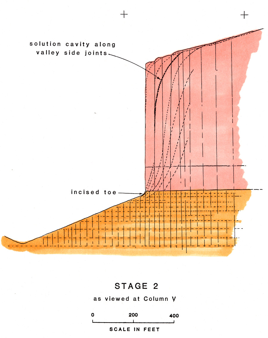
Stage 2 as viewed at Column V, with a near-vertical escarpment. At
this stage no visible failures have expressed themselves along curvilinear
secondary joints.
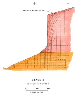
Stage 3 is observed in Column I. Here an inclined haunch has
developed in the siliceous-cemented base of the Navajo, just above
its contact with the Moenave Sandstone. The toe is inclined
about 55 degrees from horizontal and is controlled by inclined secondary
joints.
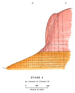
Stage 4 is depicted in Column IV. At this stage the entire column
takes on a curvalinear form, controlled by secondary joints.
Near the creast of these columns tensile separations along some of
these secondary joints were as much as 6 feet!
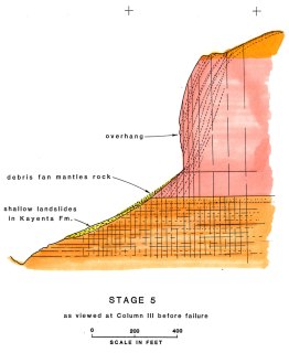
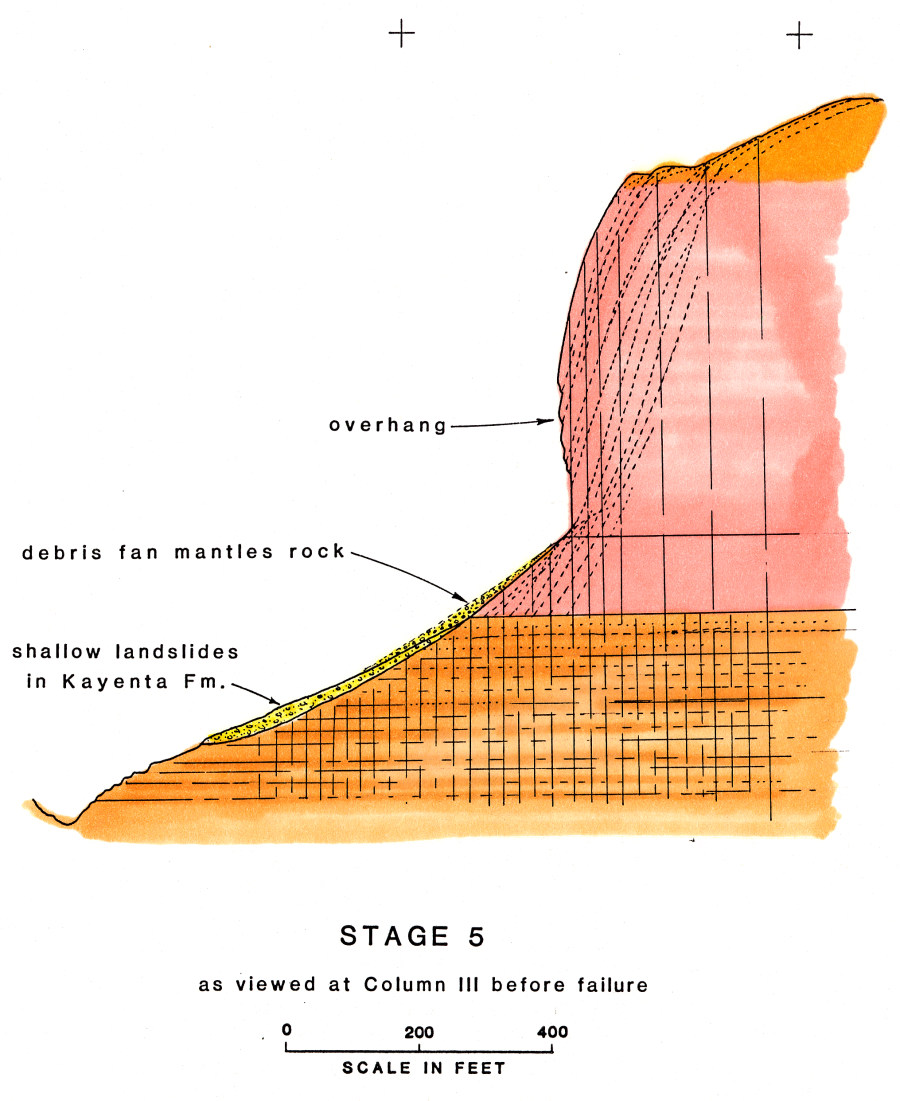
Stage 5 shows the form of Column III before the 1958 failure, based
on old surveys and photos. The column was noticeably overhung
and curvilinear. The failure was initiated by the overstressed
toe kicking out in a buckling style failure along a secondary joint
inclined at 59 degrees, removing basal support from the rock above.
Questions or comments
on this page?
E-mail Dr. J David Rogers at rogersda@mst.edu.