- The overall dimensions of the truss are established by creating a user-defined grid of joints.
- Truss members are defined by using a mouse to draw lines connecting the desired joints. The software checks the members as they are defined to ensure that the truss idealization assumptions are satisfied (i.e., members connected only at the joints)
- Supports and loads are also defined with mouse movements. The software checks to allow at least three support constraints and to accept loads only at the joints.
- Labeling of joints is performed automatically. Angles of truss members are computed and displayed as the truss is created.
- The analysis results are shown on the truss. Tension members, compression members, and zero force members are each indicated by a different color.
- Optionally, normal stresses can be computed for the truss members, or given a stress limit, the required area for each member can be computed from the results of the truss analysis.
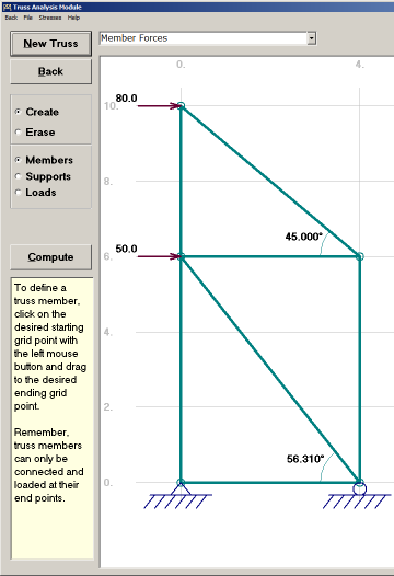
Definition of Truss
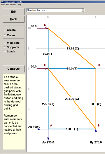
Results of Truss Analysis