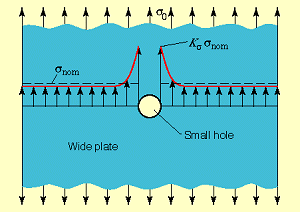
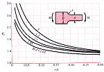
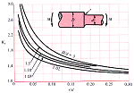
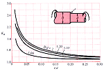
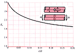
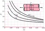
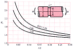
Irregularities of form such as holes, screw threads, notches, and sharp shoulders, when present in a beam, shaft, or other member subject to loading, may produce high localized stresses. This phenomenon is called stress concentration, and the form irregularities that cause it are called stress risers. The ratio of the true maximum stress to the stress calculated by the ordinary formulas of mechanics (flexure formula, torsion formula, etc.), using the net section but ignoring the changed distribution of stress, is the factor of stress concentration for the particular type of stress raiser in question.[1]
Theoretical, or geometric, stress-concentration factors are given by:
Kt = σmax / σo
Kts = τmax / τo
where the t-subscript means that the factor depends only on the geometry, instead of the material, of the part. The s-subscript stands for shear, and the o-subscript stands for nominal. We will use the standard mechanics-of-materials stress formulas for the nominal stresses. Most stress-concentration factors are determined by experimental or finite element techniques.
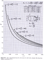
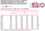
For stepped, circular shafts in torsion, Kts can be found from the following table.[2]
τmax = Kts τo
= Kts Tc / J
click to enlarge
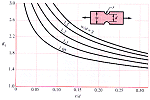
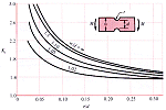
Stress-concentration factors for other geometries and loadings can be found in a similar manner.[3]
Axial Flexure Torsion Rectangular Bar Hole Notch Fillet Round Shaft Fillet Hole Groove Plate Pin Tube Hole
References
-
Roark's Formulas for Stress and Strain, by R.J. Roark and W.C. Young, 5th Edition, McGraw-Hill, 1975, p6.
-
Peterson's Stress Concentration Factors, 2nd Edition by W.D. Pilkey, et.al., John Wiley and Sons, 1997, p166.
-
Mechanical Engineering Design, 5th Edition by J.E. Shigley and C.R. Mischke, McGraw-Hill, 1989, p746-51.
