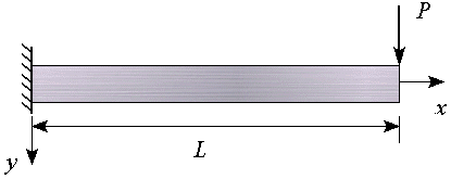
1D beam model (using Unigraphics)
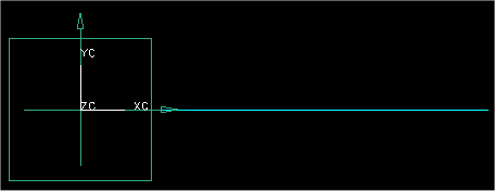
1D beam
mesh
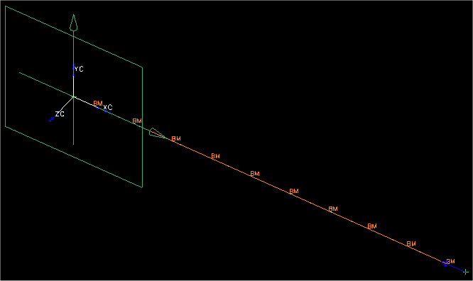
deflection
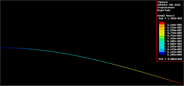
maximum
stress
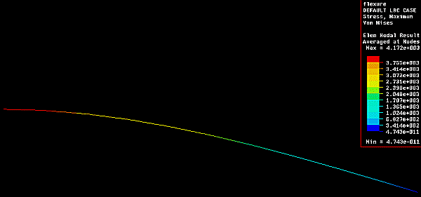
Cantilever Beam -- comparison of MoM and Finite Element Analysis (FEA)

1D beam model (using Unigraphics)
1D beam mesh

deflection
maximum stress

load variables
Load Value Description tension 100 lb load parallel to beam compression 100 lb load parallel to beam flexure 100 lb load perpendicular to beam torsion 100 in-lb moment around beam axis moment 100 in-lb moment perpendicular to beam axis length 10 in distance from support to load
material properties
Material E
(106 psi)v Material E
(106 psi)v aluminum 10.4378 0.33 nylon 0.57988 0.40 brass 14.9899 0.35 polypropylene 0.28994 0.40 copper 18.9911 0.35 steel - rolled 29.8638 0.30
cross-sectional properties
Cross-section Dimensions
(in)Iz
(in4)Iy
(in4)Jo
(in4)b = 1
h = 0.50.010417 0.41667 0.052084 r = 1 0.78540 0.78540 1.57080 b = 0.5
h = 1
t = 0.10.015 0.04225 0.5725 r = 1
t = 0.10.07854 0.07854 0.15708 b = 1
h = 0.5
t = tw = 0.10.0286583 0.00215833 0.0308167
results comparison
Cross-section Loading Material Maximum
Stress (psi)Maximum
Deflection (in)MOM 1D FEA MOM 1D FEA rectangle flexure aluminum 24000 24000 0.30657 0.3071 brass 0.21347 0.2138 copper 0.16849 0.1688 nylon 5.5182 5.528 polypro. 11.036 11.06 steel 0.10715 0.1073 rectangle tension steel 200 200 6.697E-5 6.697E-5 compression -200 -200 -6.697E-5 -6.697E-5 flexure 24000 24000 0.10715 0.1073 torsion 63.66 6.429E-4 3.043E-3 moment 2400 2400 0.16072 0.1607 rectangle flexure steel 24000 24000 0.107150 0.1073 circle 1273 1273 0.001421 0.001449 rectangular tube 20000 20000 0.074412 0.07470 circular tube 12732 3702 0.014212 0.004278 I-beam 19192 17650 0.038948 0.03628