A beam made of two or more materials is called a composite beam. We shall assume that a composite beam is constructed in such a way that it acts as a single member, as opposed to two (or more) individual beams each acting with a degree of independence and some interaction. Probably the most common composite beam is the reinforced concrete beam where the steel reinforcing and the concrete bond to form a cohesive unit. The aerospace industry utilizes many modern composite members, e.g. graphite reinforced epoxy. We shall examine a much less complex composite beam made of steel and aluminum which are bolted at intervals in an attempt to make them act as a single beam.
In the derivation of elementary flexure stress theory we made several assumptions including the assumption that our material is homogeneous and has a constant E value throughout. For many purposes it is not necessary that the material be isotropic, as long as the properties are constant throughout the cross section in the plane of the beam. Even a simple beam composed of two materials which are each homogeneous and isotropic does not satisfy the requirement that the entire beam be homogeneous. Thus elementary theory is not directly applicable.
We can apply elementary bending stress theory (or deflection theory) to our composite beam if we model it as a beam of one material. In the study of composite beams we discover that the strain distribution varies linearly from a neutral axis just as it did for homogeneous beams. However, the neutral axis of a composite beam is not at the centroid of the beam.
We construct our hypothetical model by requiring that:
- the dimensions in the loading plane are unaltered,
- the model contains only one material,
- we do not alter the strain distribution,
- the beam carries the same loading with the same deflections, and
- all other assumptions applicable in elementary bending theory have been met (e.g. linear elastic material, initially straight beam, etc.).
In fact, our transformed section (model) will differ from the actual beam in only a couple of ways. It will be composed of only one material, and the stresses in the altered portion of the cross section will differ by a constant factor from those in the actual section.
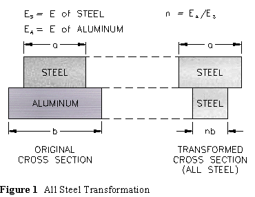
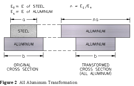
Applying the theory to obtain the transformed cross section for a simple beam of two materials is straight forward and should require no memorization of formulas. The theory simply requires that we replace one material by another while preserving the strain distribution (and thus deflections) in the beam for the same loading.
The modulus of elasticity E is a measure of stiffness. The transformed section is constructed by replacing one material with the other. Since the transformed section is to carry the same strain distribution and carry the same load as the original section, we must add (or delete) material in such a way that the load carried by the section is unaltered. Thus if we replace a less stiff material (low modulus of elasticity) with a stiffer material (higher modulus of elasticity) we will need less of it by the ratio of the E values. On the other hand, if we replace a high modulus material with a lower modulus material we need more material.
Any dimensional changes are made in the plane perpendicular to the loading plane. Since we usually assume the loading plane to be vertical, the dimensional changes would occur in the horizontal plane. Consider the following two transformations:

After the section is transformed all calculations are made using the transformed cross section, just as they would be on a beam of one material. The neutral axis of bending is at the centroid of the transformed section and flexure stresses are calculated with the flexure stress formula.
One final step is required to return to the original cross section. If in going from the stress state in the transformed material we find a reduction in area then we must increase the stresses accordingly to carry the same load. Conversely if we increase area then we reduce stress. Those portions of the cross section which were unaltered in the transformation process carry the same stresses on both the original and transformed sections.
The objective of this experiment is to measure the maximum fiber strains at a particular cross section of a simply supported elastic beam of two materials, and to use the measured strains to determine the experimental maximum fiber stresses. These maximum fiber stresses will then be compared with the values predicted from the theory utilizing the transformed section.
- Simply support a composite beam of two materials.
- Record load location, strain gage locations, span of beam and cross-section dimensions on a sketch of the beam and its cross section.
- Record modulus of elasticity values for the beam materials.
- Load the beam in uniform increments and record the strain gage readings for each load. Record strain reading for about ten values of load.
- Multiply your strain values by the appropriate elastic modulus to obtain stress values.
- Plot the flexure stress values vs load.
- Determine the stress per unit load values using the method of least squares.
- Calculate the theoretical stress per unit load values using the transformed section and the flexure formula.
- Compare the flexure stresses per unit load obtained from the experimentally measured strains with those obtained from theory.
- Use the experimental strains to locate the neutral axis of the beam cross section using the assumption of linear variation of flexural strain with respect to perpendicular distance from the neutral axis. Compare this value with that obtained by locating the centroid of the transformed section.
- What ratio of elastic moduli n = EST/EAL of the beam materials would give a theoretical (transformed section method) neutral axis location that agrees with the experimental location determined in 6 above?
Given:
EST = 28 x 106 psi
EAL = 10.6 x 10⁶ psiDetermine:
Theory Experiment 1. _______ psi/lb _______ psi/lb 2. _______ psi/lb _______ psi/lb 3. y (neutral axis from bottom) _______ inches _______ inches 4. 2.64 _______ 5. INA (for section transformed to aluminum) _______ in4
Mechanics of Materials, by Higdon et.al., 4th Ed., Wiley, 1985, pp 336-339.
Mechanics of Materials, by Hibbeler, Macmillan, 1991, pp 281-283.
Mechanics of Materials, by Hibbeler, Macmilian, 2nd Ed, 1994, pp 321-325.


