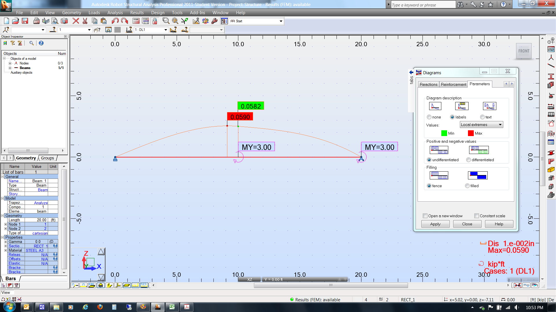
To find the beam's deflection at a particular point, you may have to draw an extra node at that point (go to Geometry, Nodes). After doing Analysis, Calculations, go to Results, Diagrams for Bars. Select the Deformation tab and then check "Exact deformation for bars". Then go to the Parameters tab and check "labels" and click Apply. That should show the maximum deflection and the deflection at various nodes.

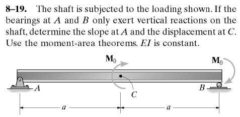
vC = M0 a2 / 4EI (up)
= (3 ft-kip) (10 ft)2 (12in./ft)3 / 4 (29,000.02 ksi) (76.8 in.4)
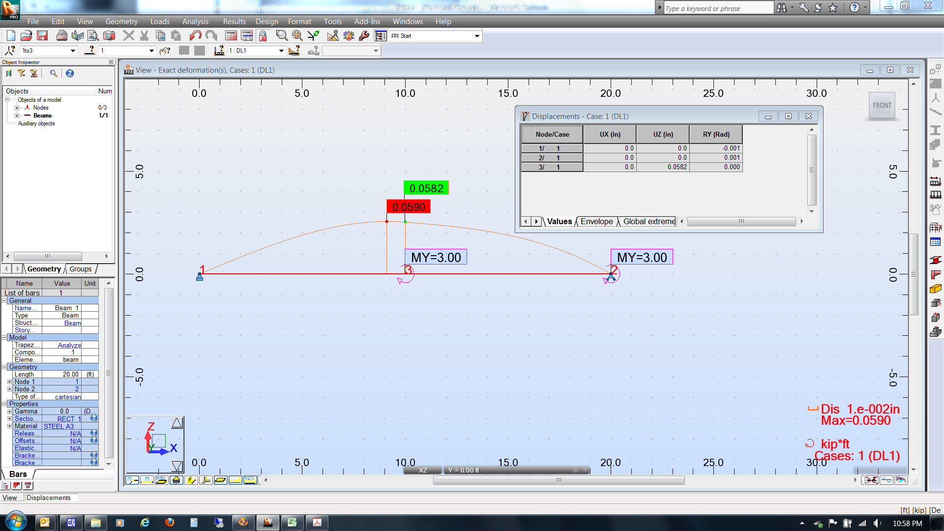
Alternatively, you can go to Results, Displacements to see the deflection values in a table. UZ is the vertical deflection. RY is the slope, but it may be too small (in radians) for Robot to show more than one significant figure. Significantly increasing the loads and lengths may create enough of an angle for you to compare to your derivations. If not, then just focus on the displacement(s).
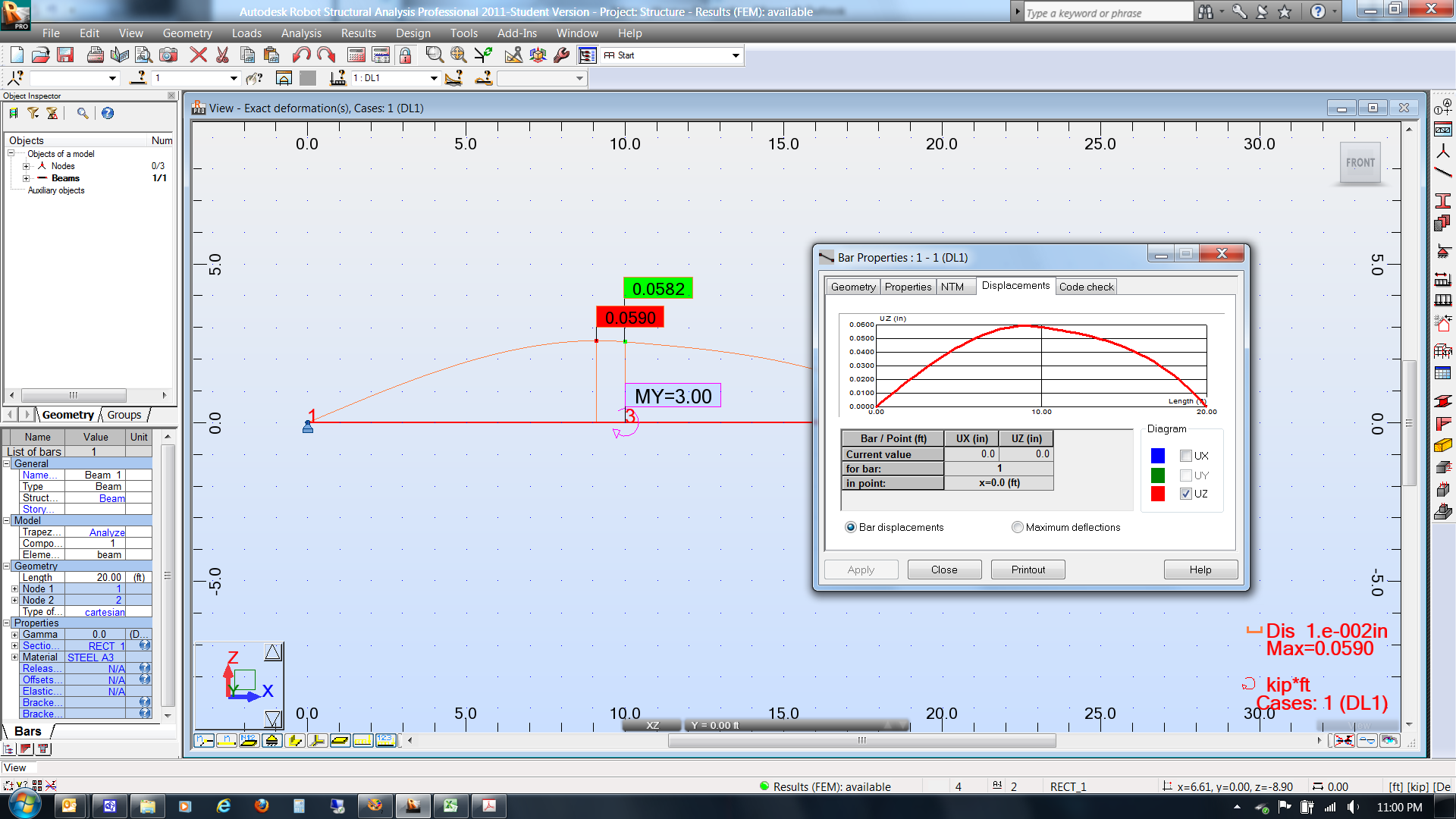
If all else fails, you can right-click on the beam, select Object Properties, go to the Displacements tab, and check UZ. This deflection graph can be used to find the (approximate) deflection values all along the beam.