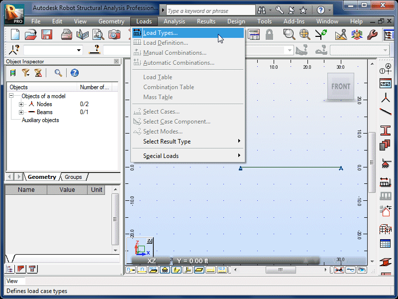
| Select Loads and Load Types. |
|
 |
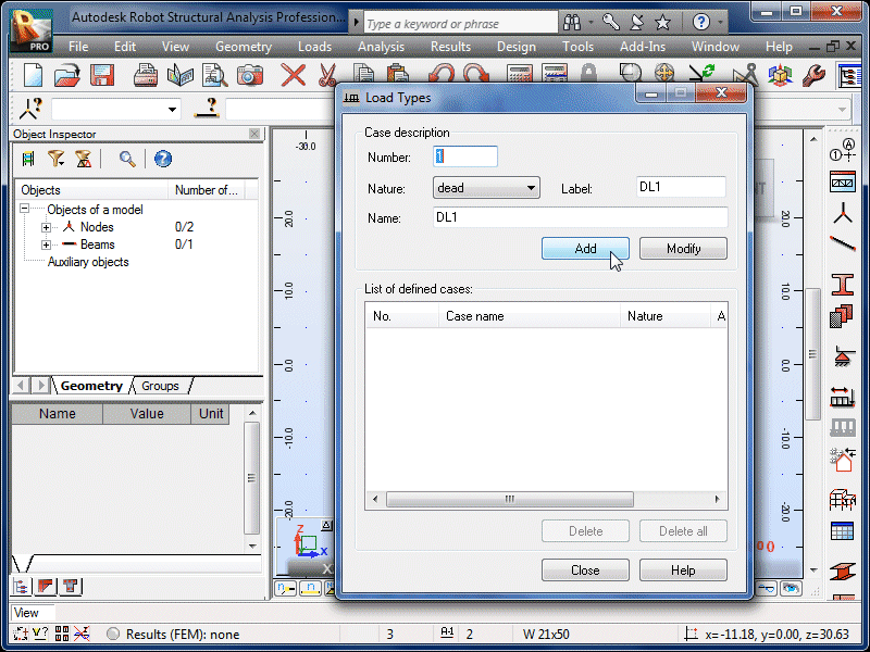
| Select Add to accept the default dead-load
options. |
|
 |
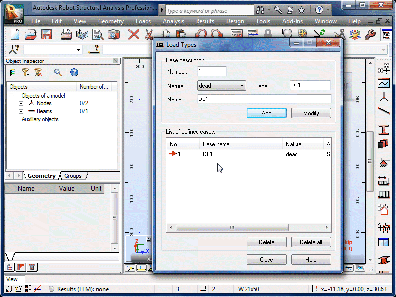
| This will be the only load case needed for this
problem. We will add the particular load details
in the next steps. |
|
 |
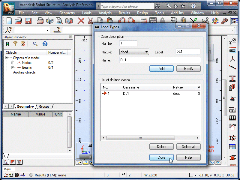
| Select Close. |
|
 |
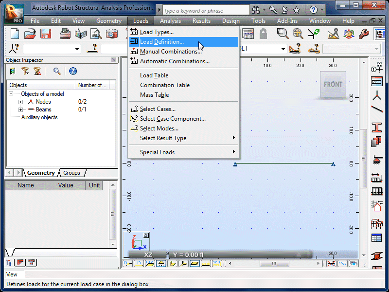
| Select Loads and Load Definition. |
|
 |
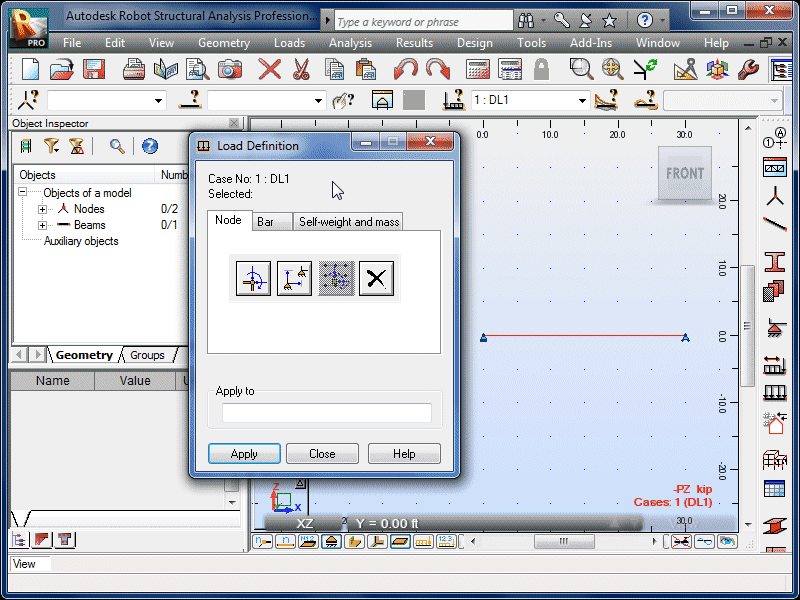
| The Load Definition window will appear. |
|
 |
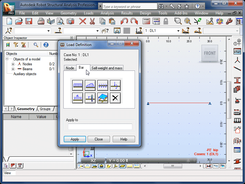
| Select the Bar tab. |
|
 |
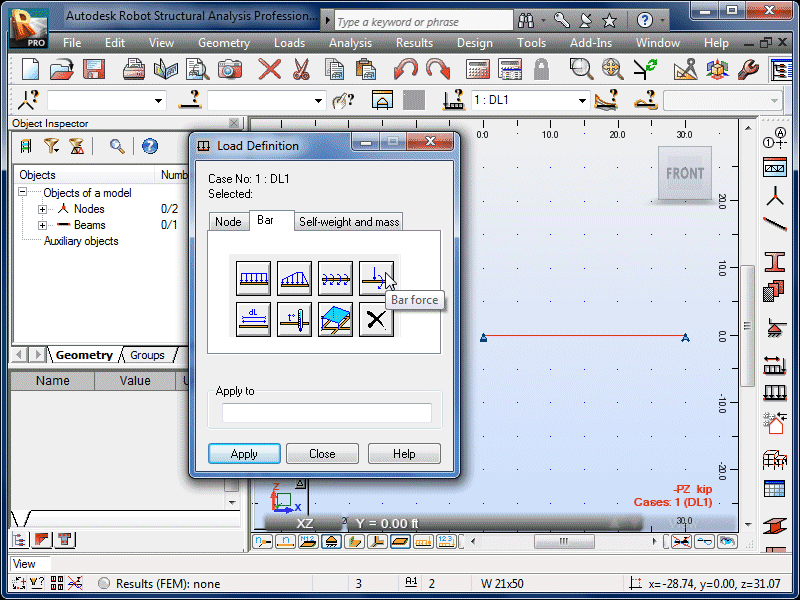
| Select the Bar Force icon to define a
concentrated force. |
|
 |
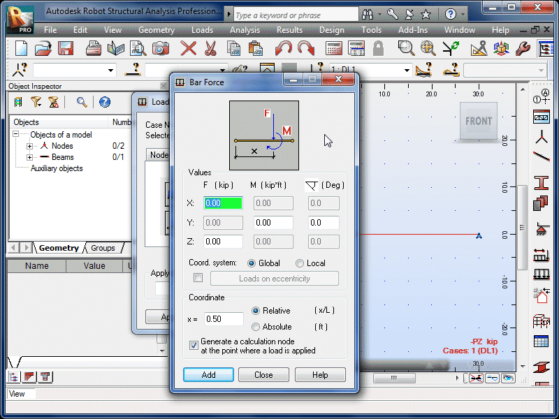
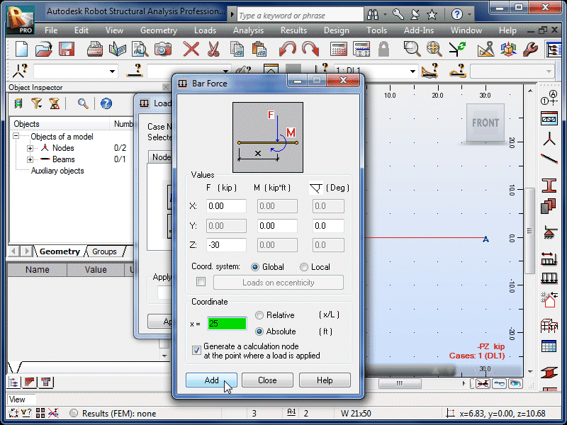
| The Bar Force options window will appear. |
|
 |
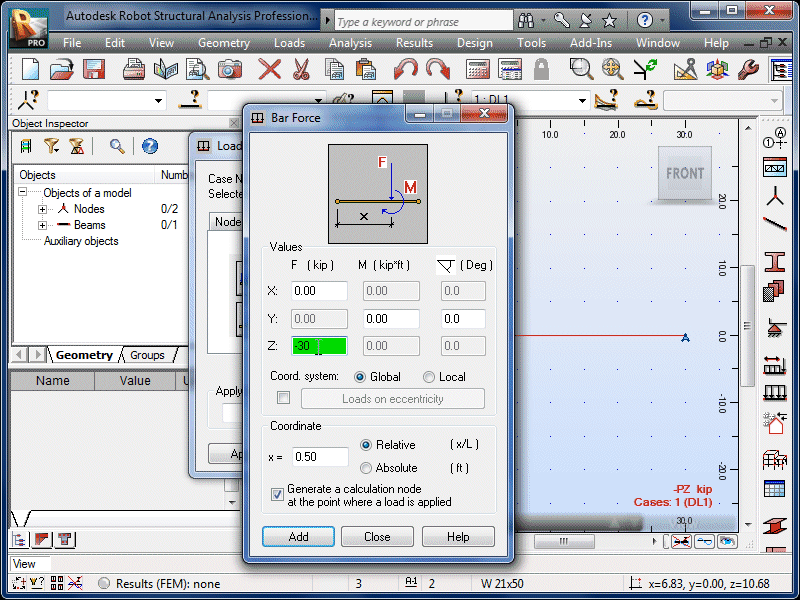
| Enter the magnitude and direction (negative z-direction
for down). |
|
 |
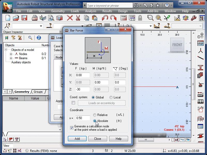
| Select the Absolute coordinate option. |
|
 |
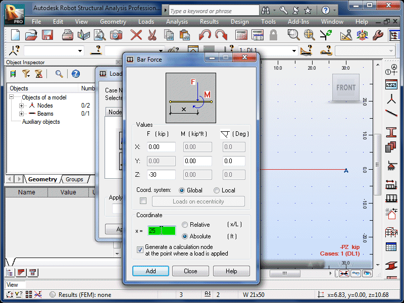
| Enter the distance between the left end of the beam
and the concentrated force. |
|
 |
| Select Add. |
|
 |
| Move the options window until the beam is
visible. Click anywhere on the left half of the
beam. |
|
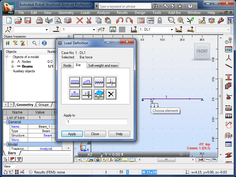 |
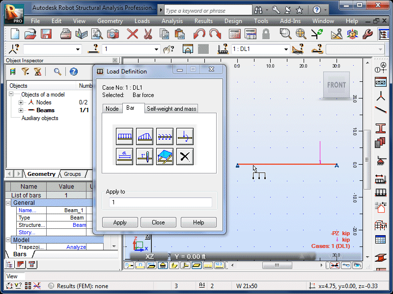
| The concentrated force will now appear on the beam. |
|
 |
| If you accidentally click on the right half of the
beam, the load coordinate will be measured from the
right end. |
|
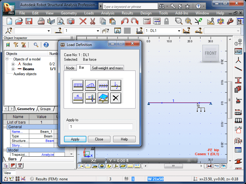 |
| And the load will be in the wrong location. If
this happens, simply Undo. |
|
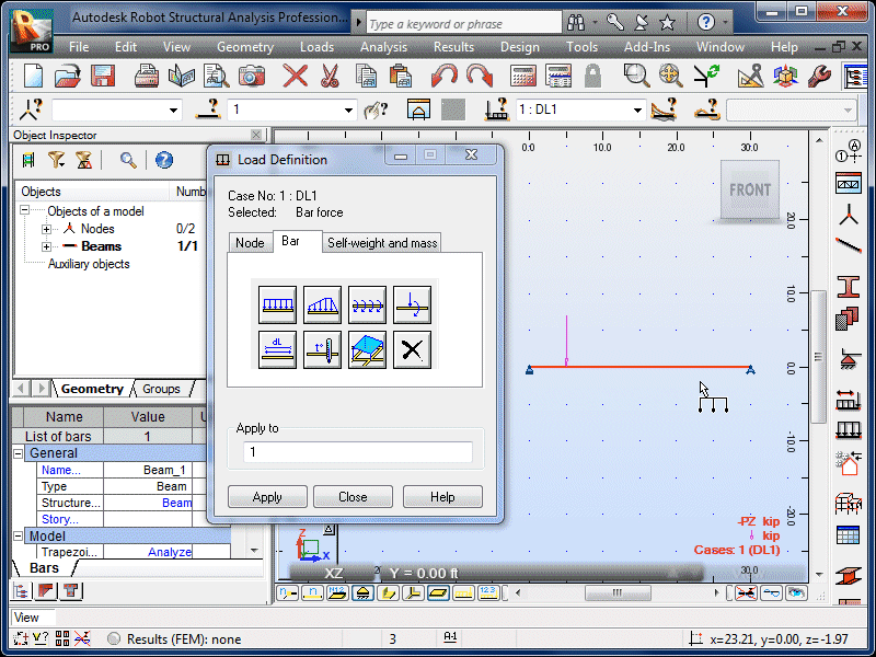 |
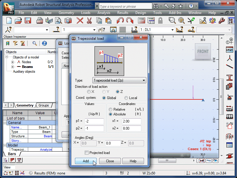
| Select the Trapezoidal Load icon. |
|
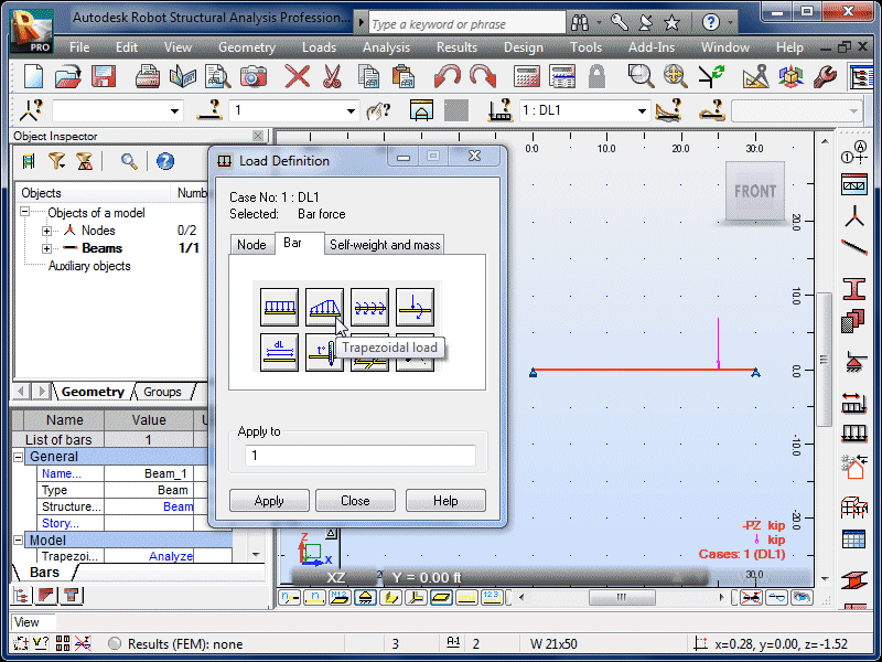 |
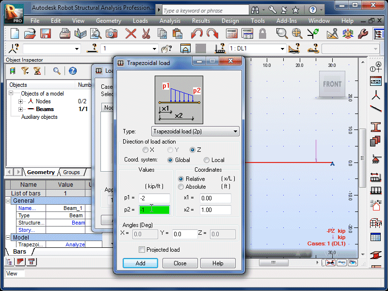
| The default is a simple trapezoidal load with starting
and ending magnitudes of p1 and p2. |
|
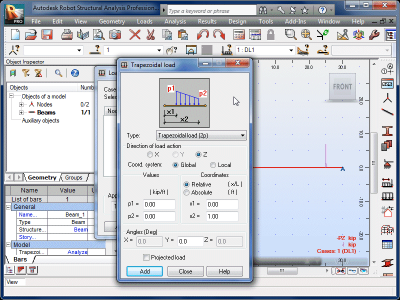 |
| Enter the starting magnitude and direction (negative
for down). |
|
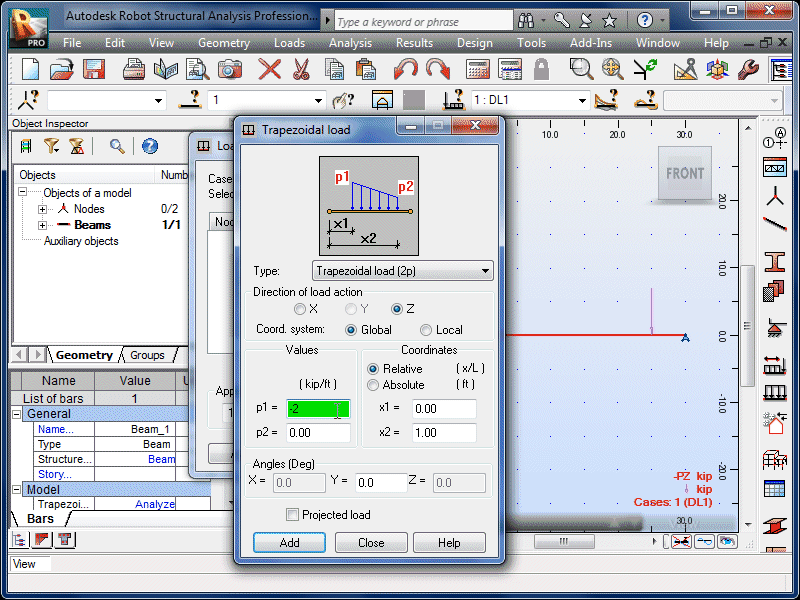 |
| Enter the ending magnitude and direction. |
|
 |
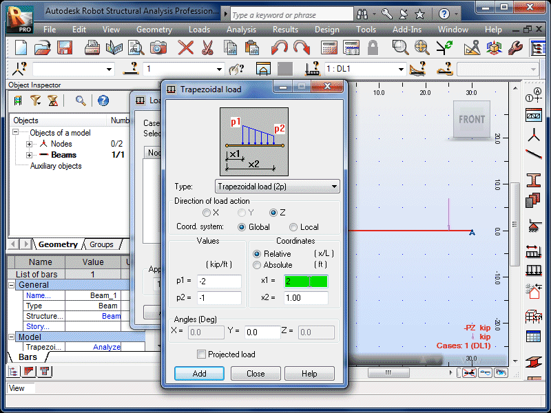
| Enter the starting coordinate, measured from the left
end of the beam. |
|
 |
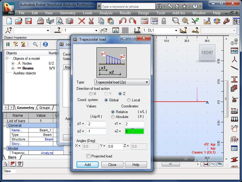
| Enter the ending coordinate. |
|
 |
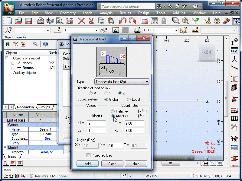
| Select the Absolute coordinate option. |
|
 |
| Select Add. |
|
 |
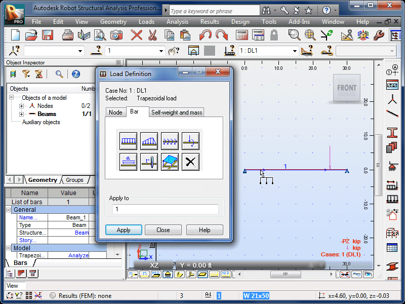
| Click anywhere on the left side of the beam. |
|
 |
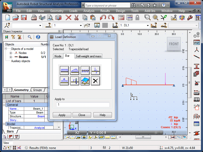
| The trapezoidal load will now appear on the beam. |
|
 |
| Select the Trapezoidal Load icon again. |
|
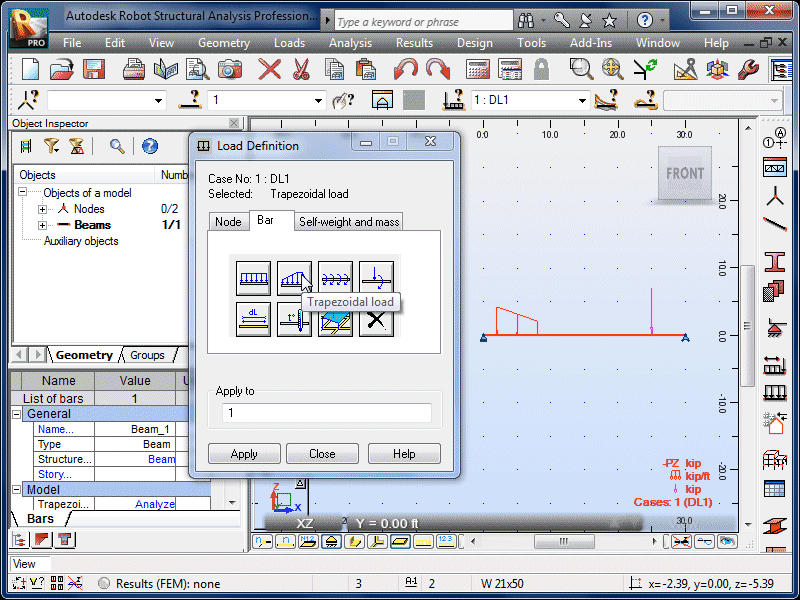 |
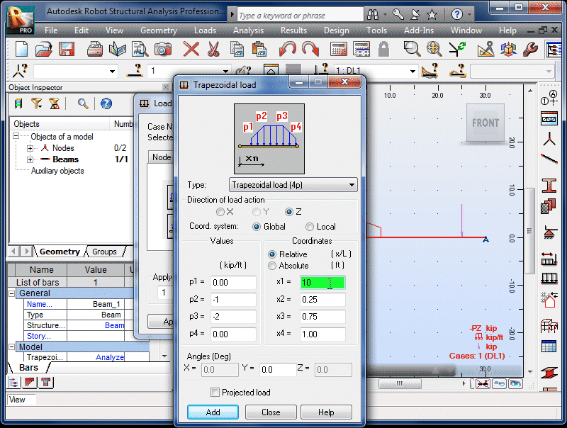
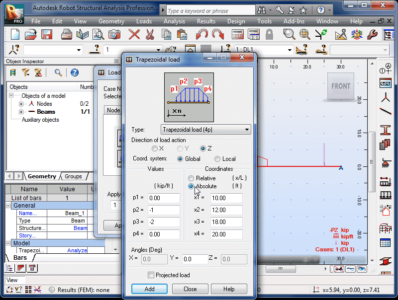
| Select the four-point trapezoidal load option from the
pull-down menu. |
|
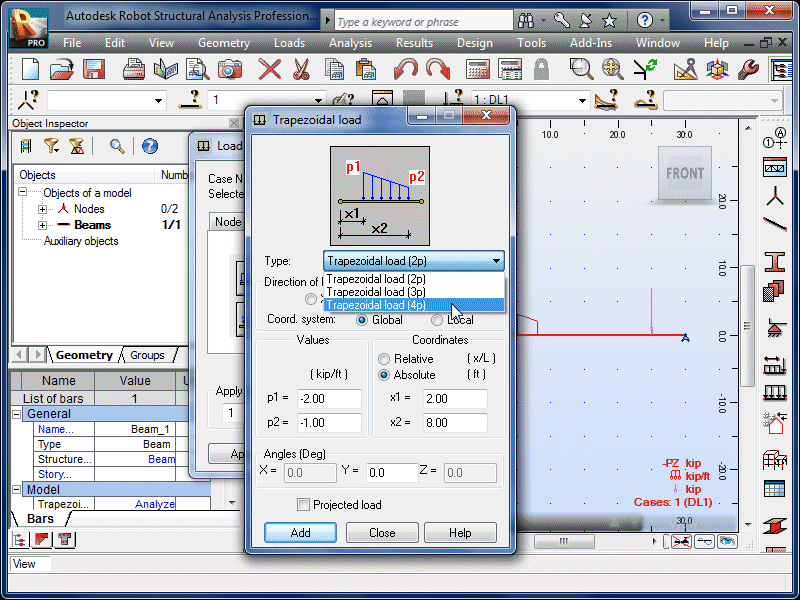 |
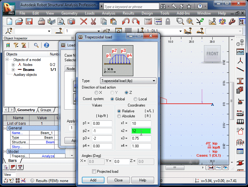
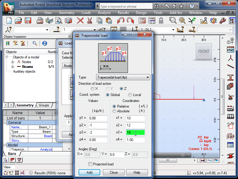
| This loading is defined by magnitudes p1, p2,
p3 and p4. Note that these values
can be zero. |
|
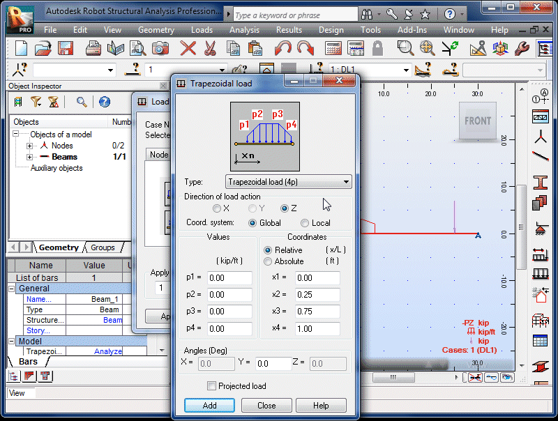 |
| Enter the first non-zero magnitude and direction. |
|
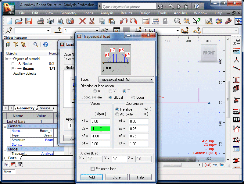 |
| Enter the other non-zero magnitude and direction. |
|
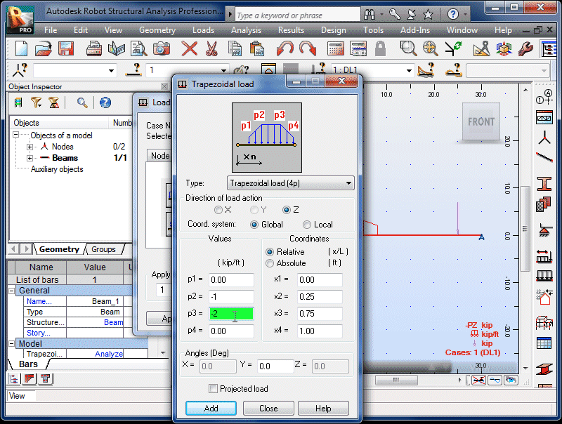 |
| Enter the coordinates corresponding to p1
through p4. |
|
 |
|
|
 |
|
|
 |
|
|
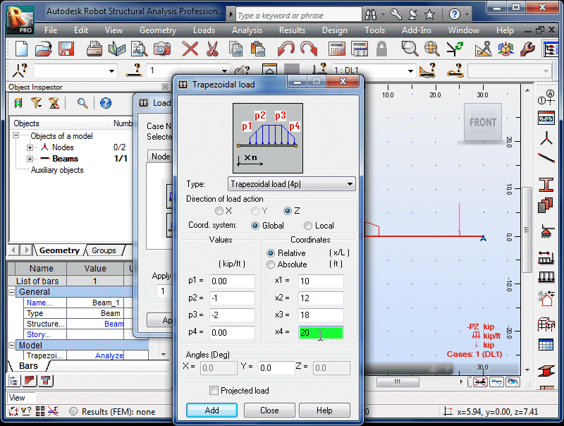 |
| Select the Absolute coordinate option and Add. |
|
 |
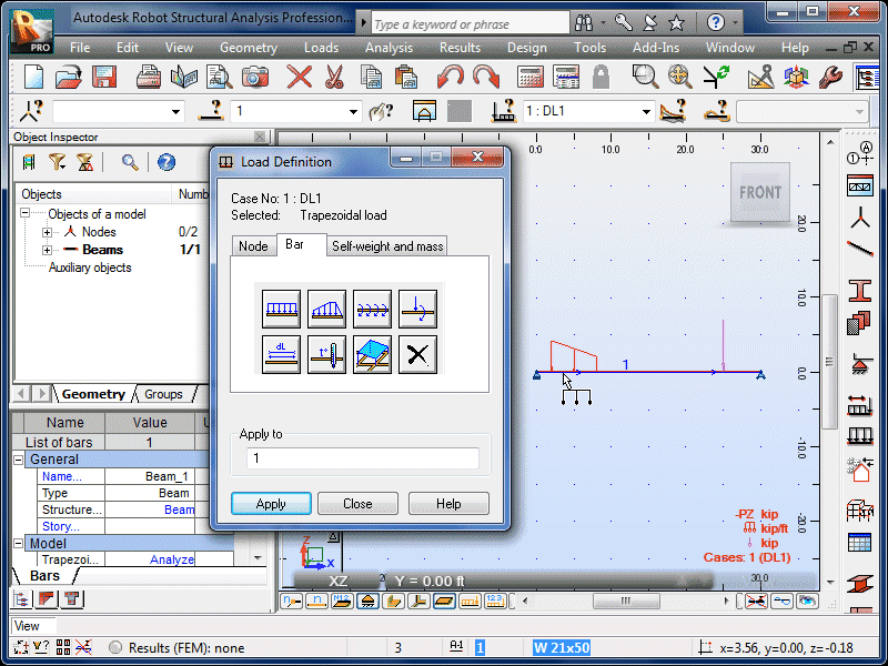
| Click anywhere on the left half of the beam. |
|
 |
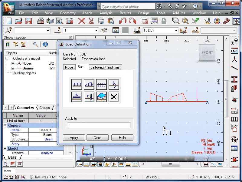
| The second trapezoidal load will now be visible on the
beam. |
|
 |
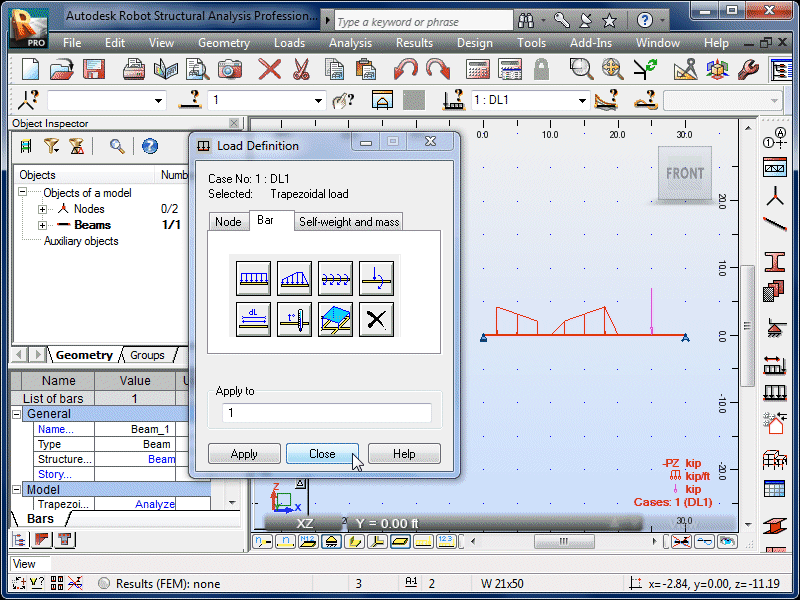
| Select Close. The loads will no longer be
visible, but they are still defined and applied to the
beam. |
|
 |
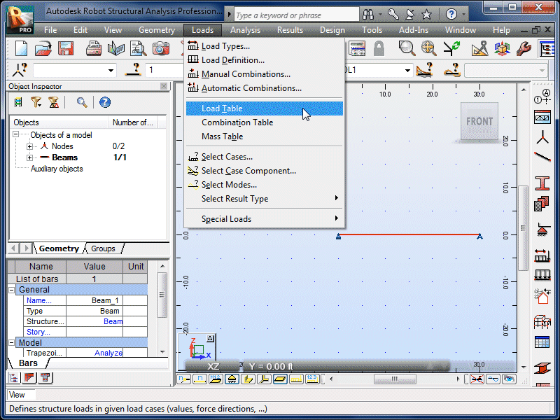
| Select Loads and Load Table. |
|
 |
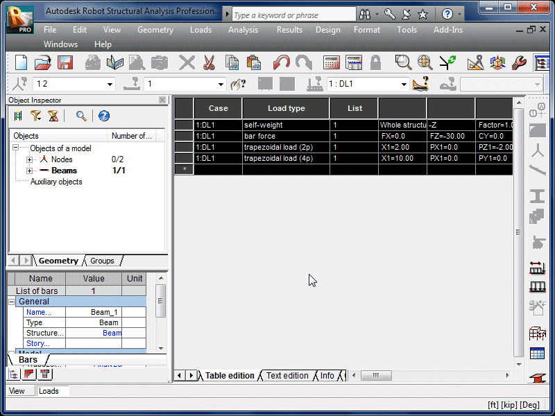
| This table summarizes the loads currently present on
the beam. Note that the beam's self weight is
automatically included. |
|
 |
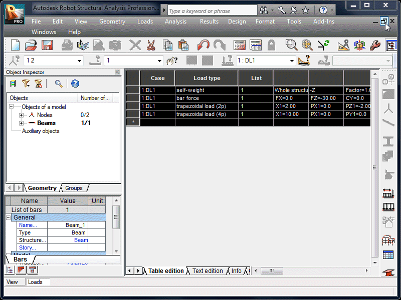
| Select the Restore Down icon. |
|
 |
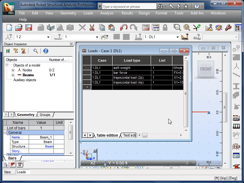
| Close the load table. |
|
 |
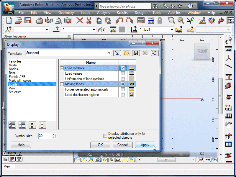
| Select View and Display. |
|
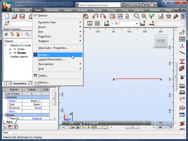 |
| The Display window can be used to change how
the beam appears on the screen. |
|
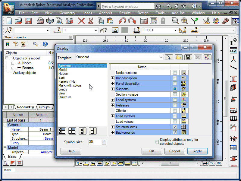 |
| Select the Loads option. |
|
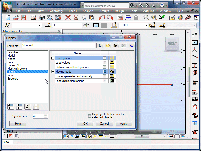 |
| Select Load Symbols. |
|
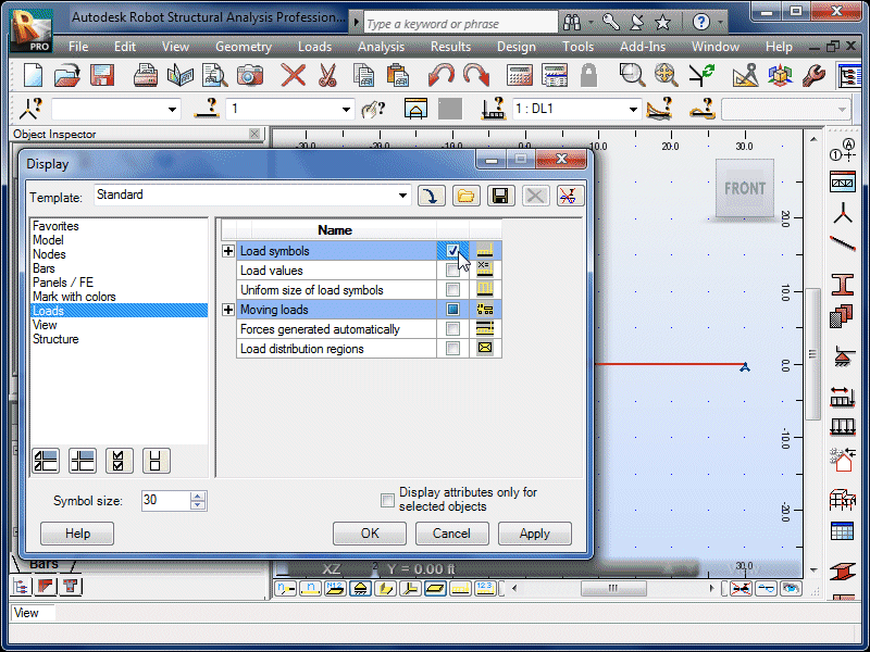 |
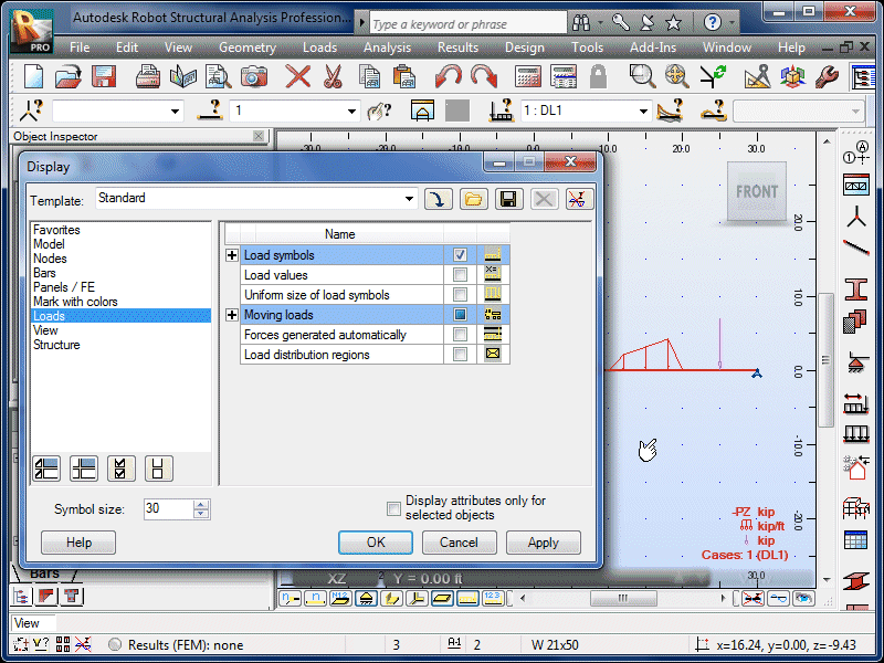
| Select Apply. |
|
 |
| Note that the loads are now visible again. Feel
free to try other Display options. |
|
 |
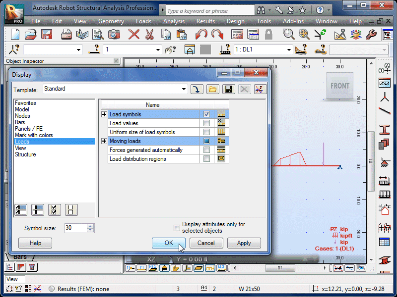
| Select OK. |
|
 |


