| Click here to
view larger images. Or select an individual image to view it at full size. |
||
| Select Analysis and Calculations. | 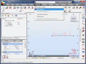 |
|
| There will be no visible change on the screen, but results may now be accessed. | 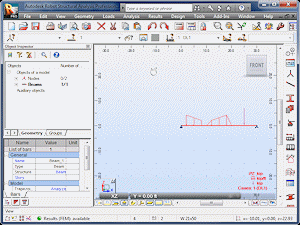 |
|
| Select Results and Reactions. | 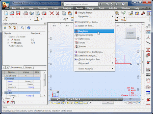 |
|
| Nodes 1 and 2 represent the left and right ends of the beam. FX, FZ and MY represent the ground reactions at the pinned and roller supports. | 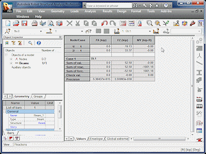 |
|
| The Reactions table is covering the image of the beam. Select the Restore Down icon to expose both windows. | 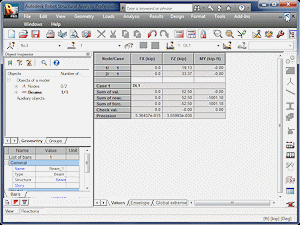 |
|
| Feel free to close the Reactions window. | 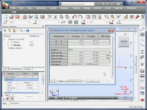 |
|
| Select Results and Deflections. | 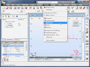 |
|
| UZ represents the beam's movement in the z-direction. | 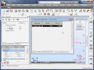 |
|
| Select Results and Detailed Analysis. | 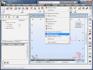 |
|
| Two windows will appear. One can be used to select the options that will appear in the other. | 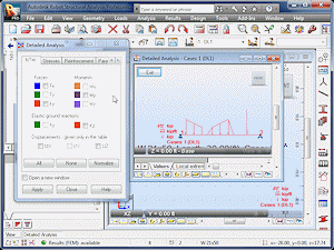 |
|
| Select Fz. | 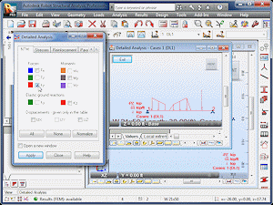 |
|
| Select Apply. | 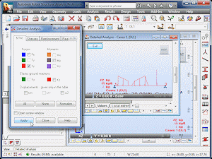 |
|
| A shear-force diagram will appear above the beam. | 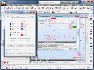 |
|
| Select My. | 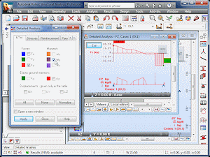 |
|
| Select Apply. | 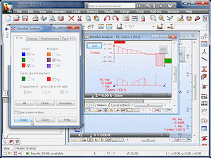 |
|
| Shear-force and bending-moment diagrams will now be visible. | 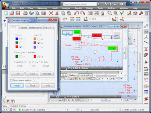 |
|
| To remove the diagrams, deselect Fz and My
and select Apply.
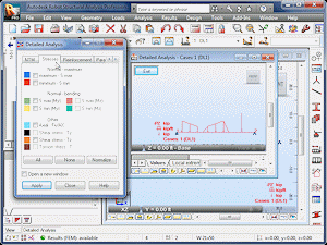
Select the Stresses tab. |
 |
|
| Select S max, which represents the maximum normal stress due to bending. | 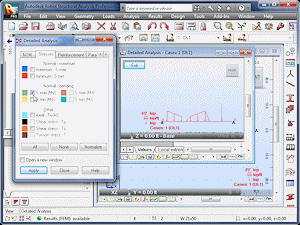 |
|
| Select Apply. | 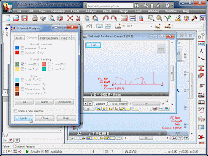 |
|
| A diagram will be visible showing the maximum normal stress along the beam's length. | 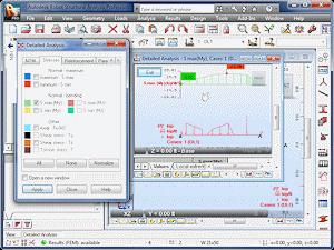 |
|
| Select Shear stress Tz, which represents the horizontal shear stress. | 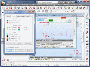 |
|
| Select Apply. | 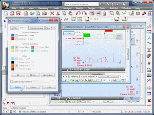 |
|
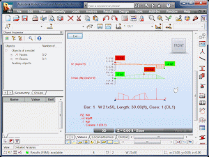
| Both stress diagrams will now be visible. | 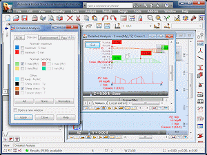 |
|
| Maximize the diagram window. | 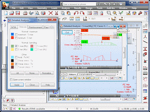 |
|
| Close the options window. | 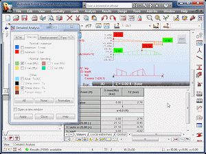 |
|
| Drag the divider between the diagram and table areas downward to get a better view of the diagrams. | 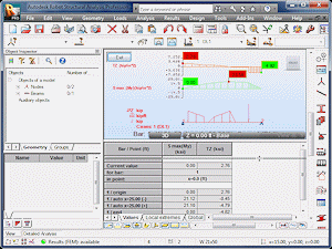 |
|
 |