| Click here to
view larger images. Or select an individual image to view it at full size. |
||
| We will create influence lines for problem 6.11 in this tutorial. | 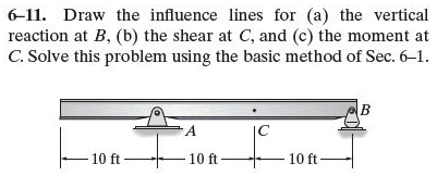 |
|
| Select the appropriate model for your homework problem (Frame 2D in this case). |  |
|
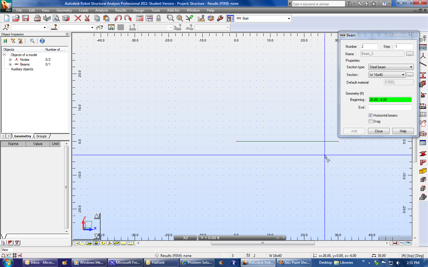
| Draw the structure. | 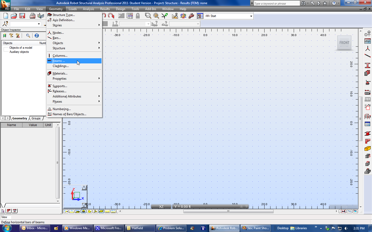 |
|
 |
||
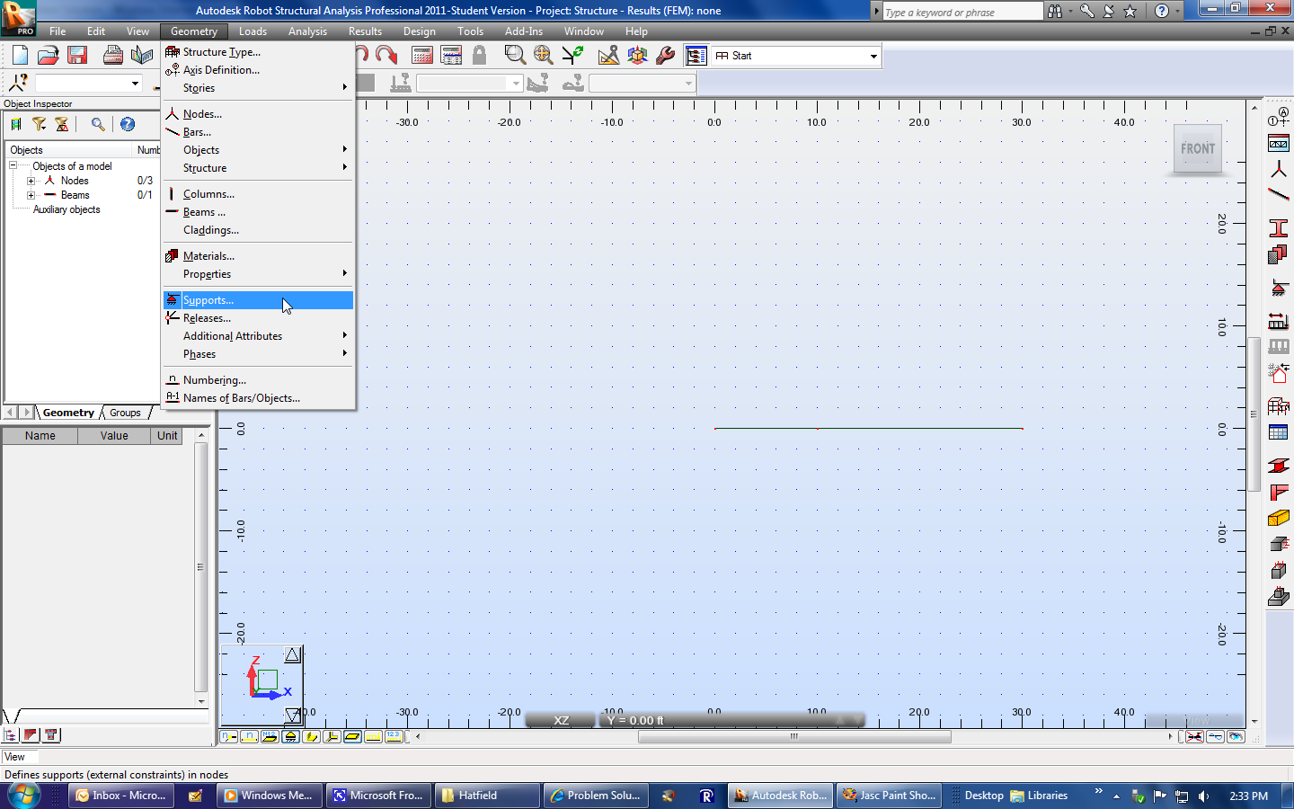
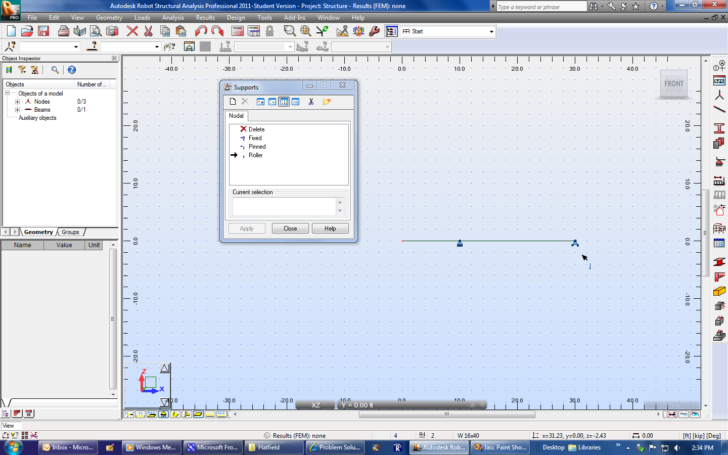
| For this problem, an extra node is needed at point
A. This will allow the pin support to be added
there.
Add the supports. |
 |
|
 |
||
| Go to Loads, Special Loads, Moving. | 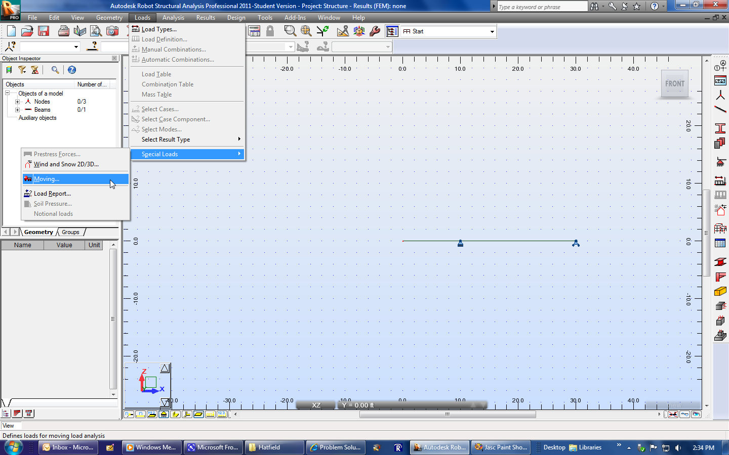 |
|
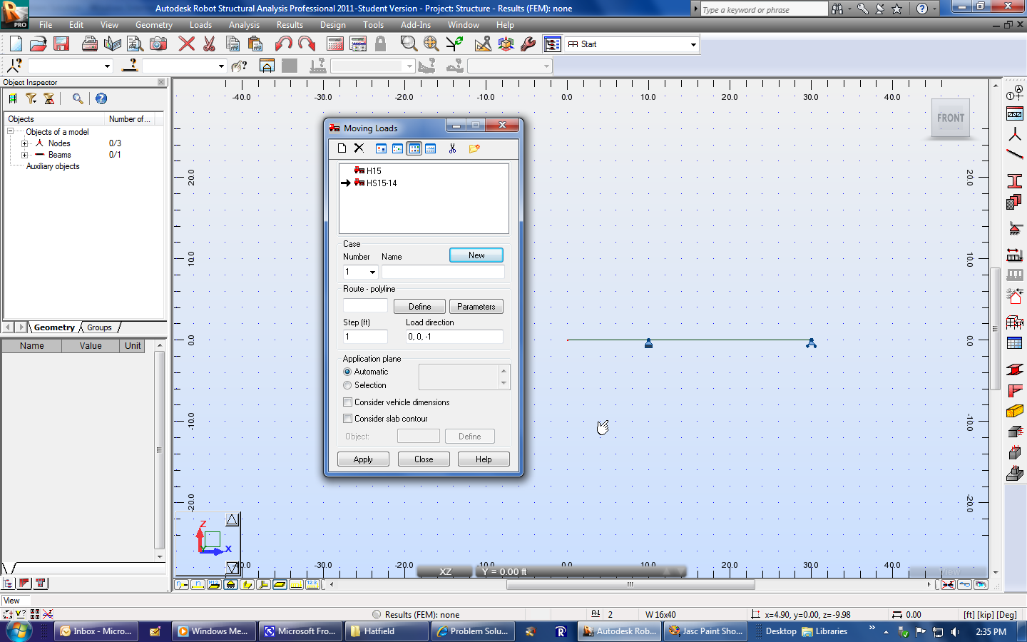
| The Moving loads window will appear. Note
that a pair of standard trucks are available to use.
We will need to add a new, and very simple, moving load. Select the New Vehicle icon at the top left (it looks like a sheet of paper). |
 |
|
| Another window will appear that shows details for one of the existing trucks. |  |
|
| Select the New button. | 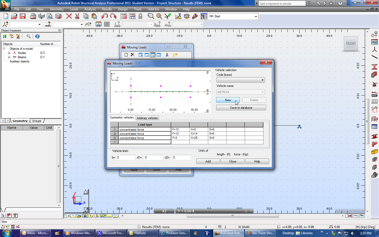 |
|
| Enter a name for the new vehicle. | 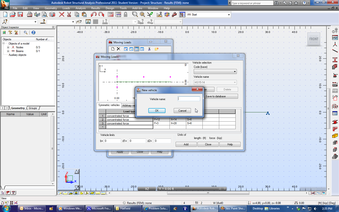 |
|
| Use something like "Unit Load (kips)" if you are using Imperial units or "Unit Loads (kN)" if you are using metric units. Select Ok. |  |
|
| Select the Load type pull-down menu. |  |
|
| Select the concentrated force option. | 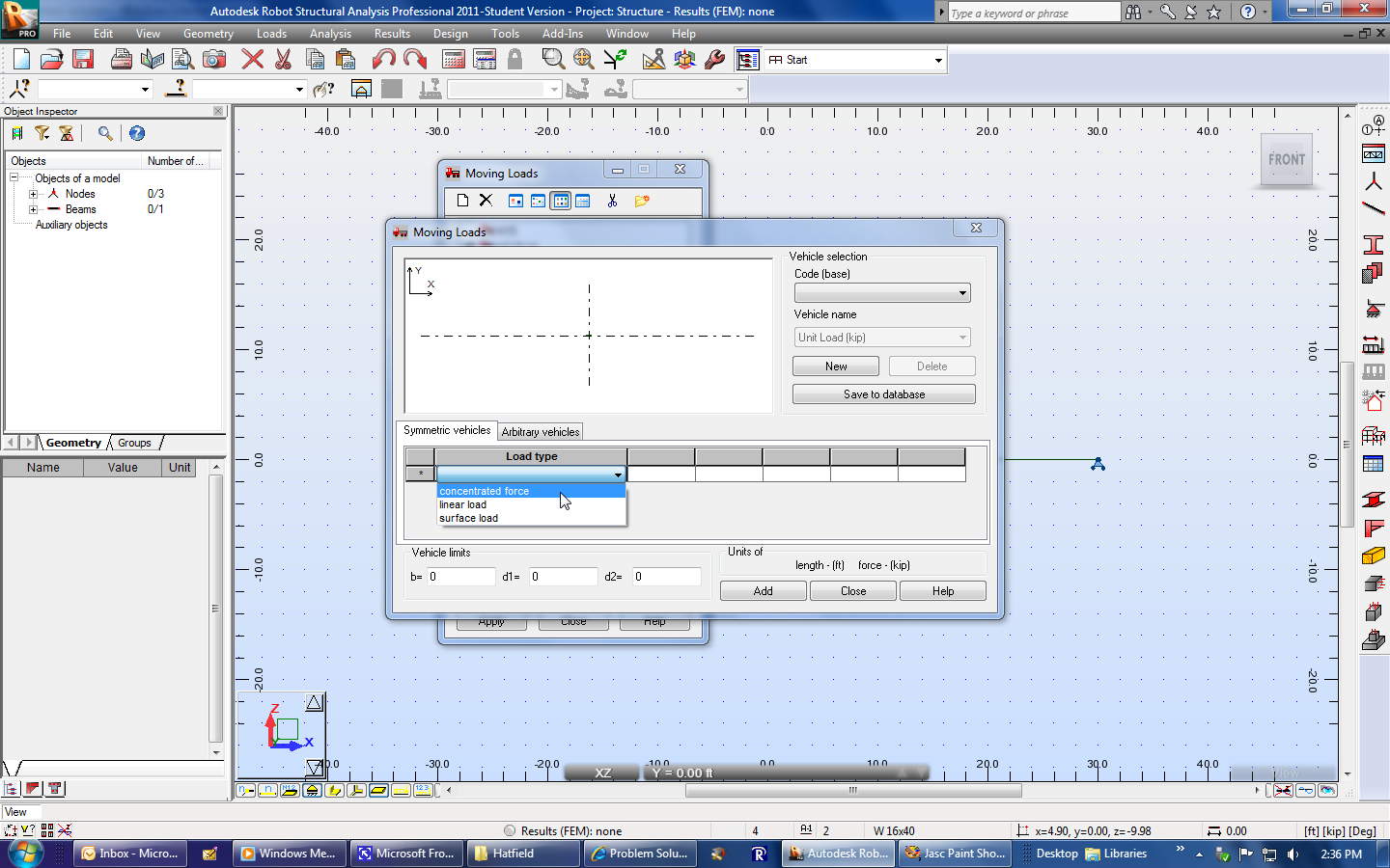 |
|
| The default concentrated force will have zero magnitude. |  |
|
| Change "F=0" to "F=1" in order to model a unit load. | 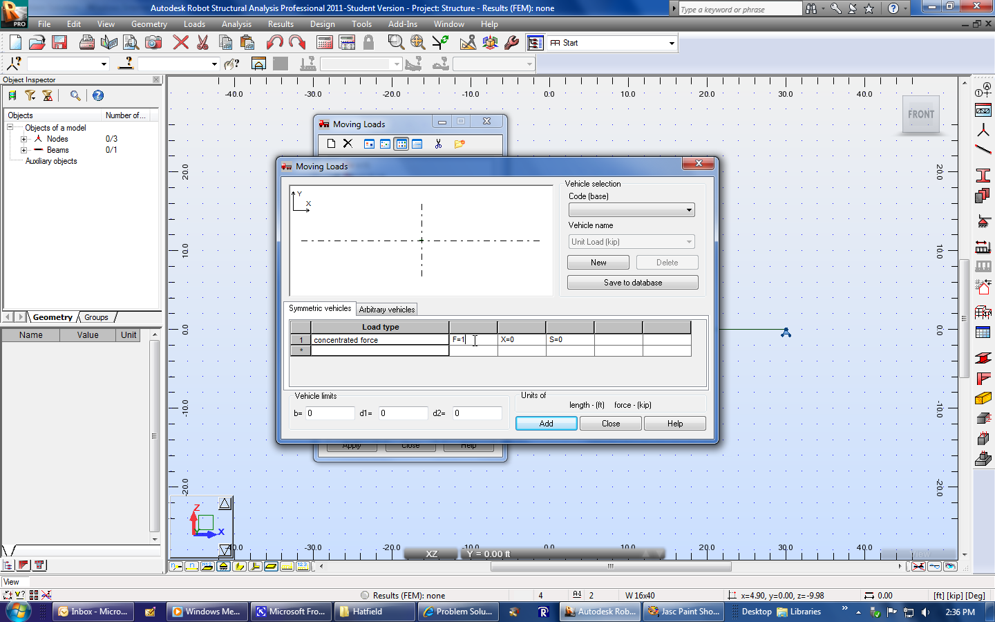 |
|
| Select Save to database and then Ok in the pop-up window. | 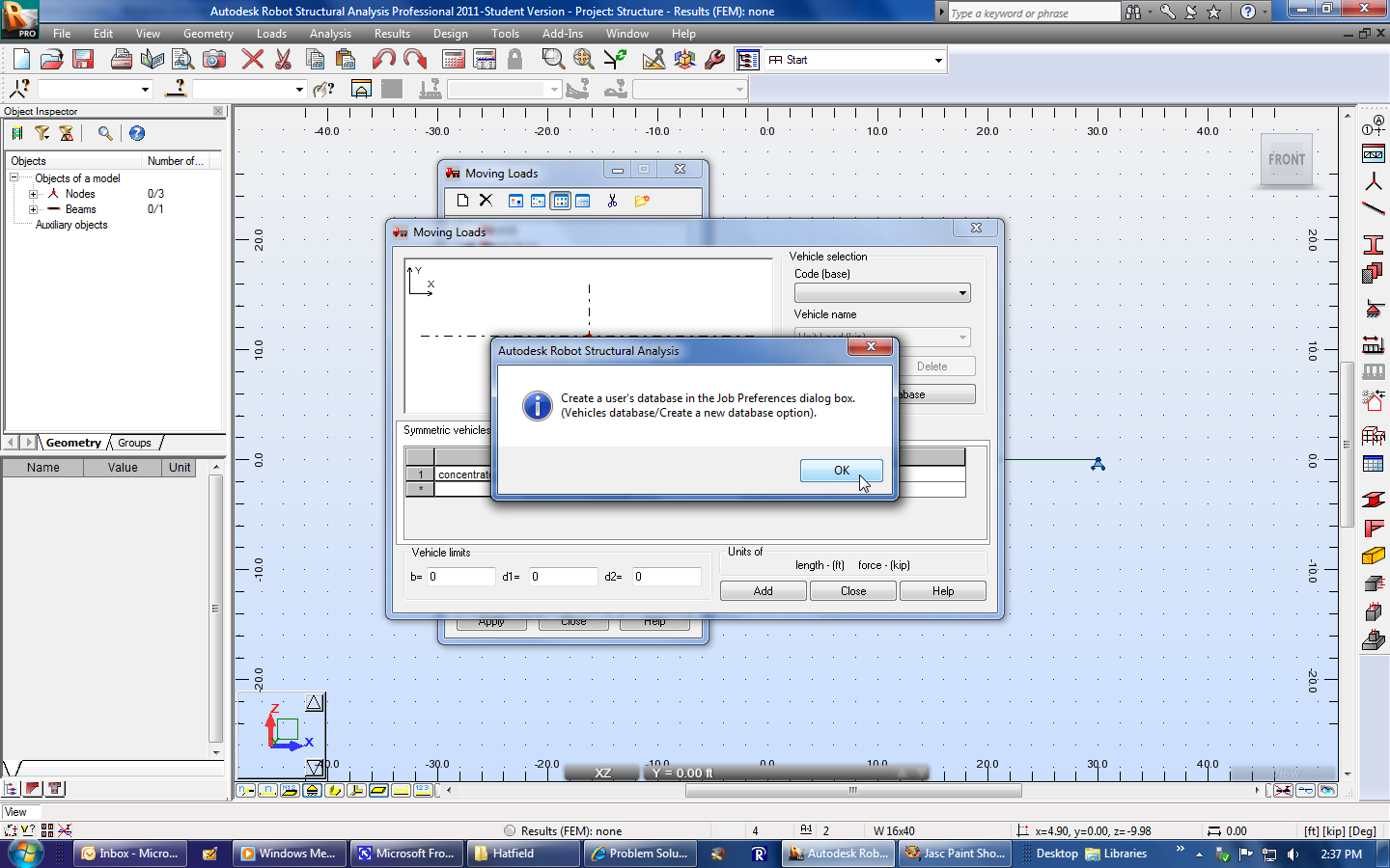 |
|
| Select Add. | 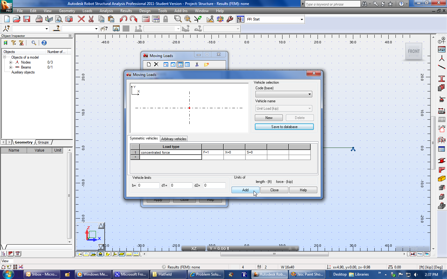 |
|
| Select Close. | 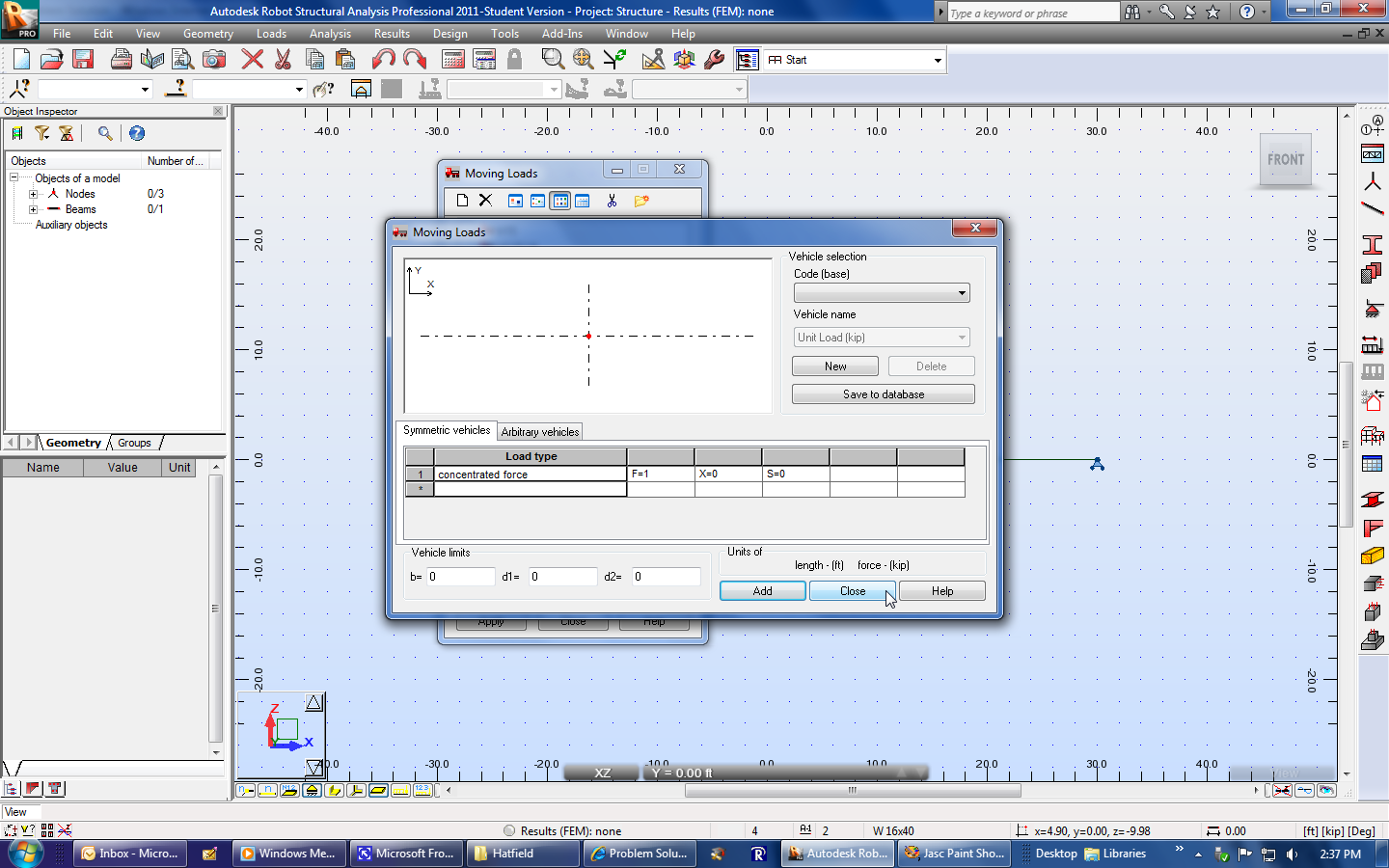 |
|
| The new unit-load vehicle should appear next to the default trucks. | 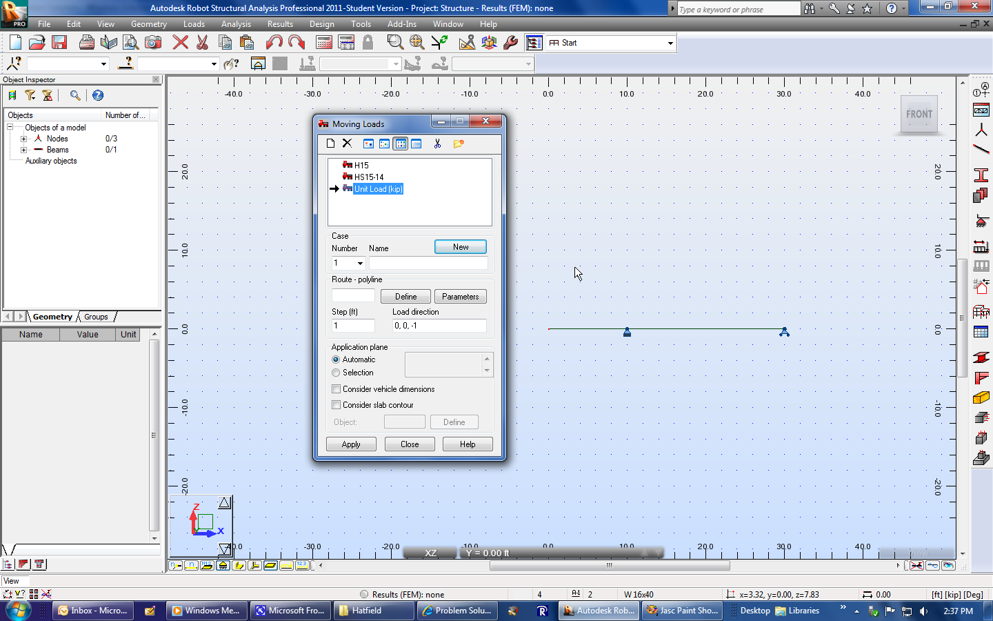 |
|
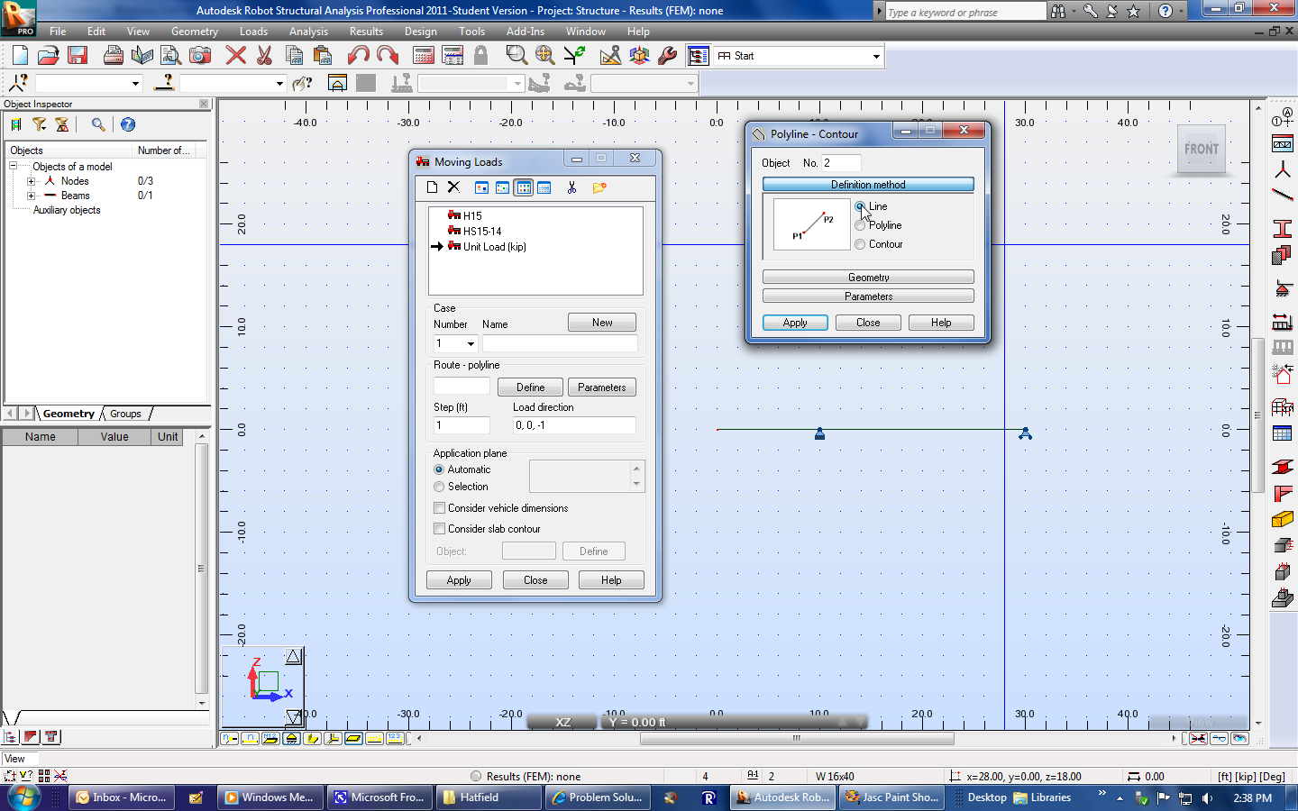
| Select Define in order to define the path the unit load will follow across the structure. | 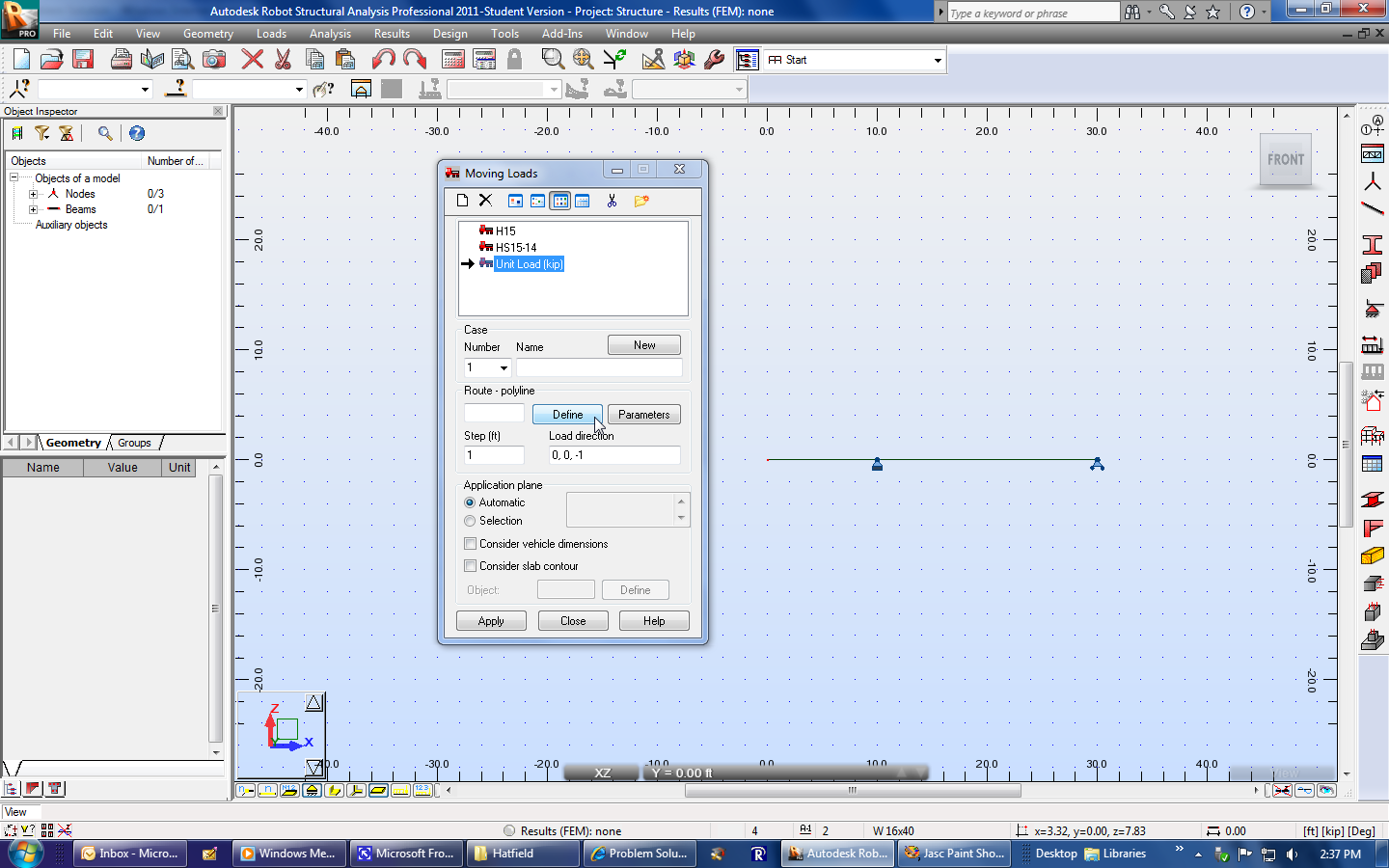 |
|
| Change the Polyline option to Line. |  |
|
 |
||
| Select Geometry. | 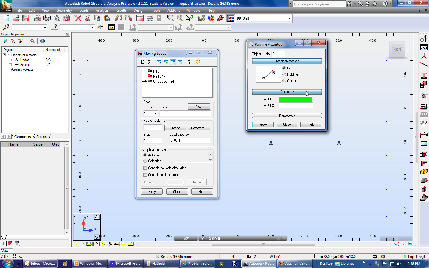 |
|
| Select Point P1. |  |
|
| Select the left end of the structure. |  |
|
| And then select the right end. Manually edit the numbers if necessary. This will cause the unit load to pass left-to-right on the structure. | 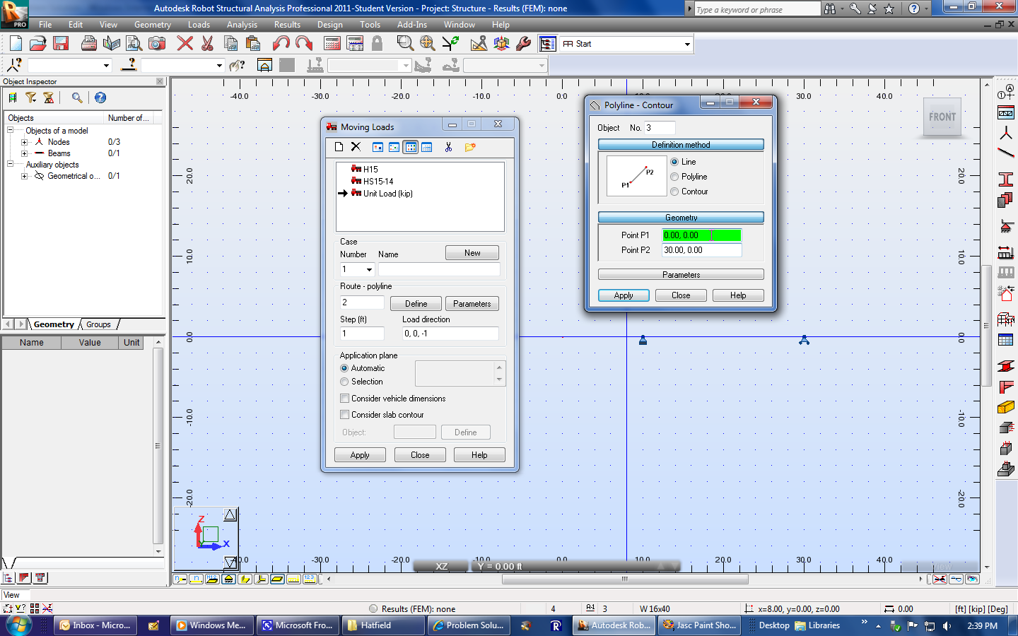 |
|
| Select Apply. | 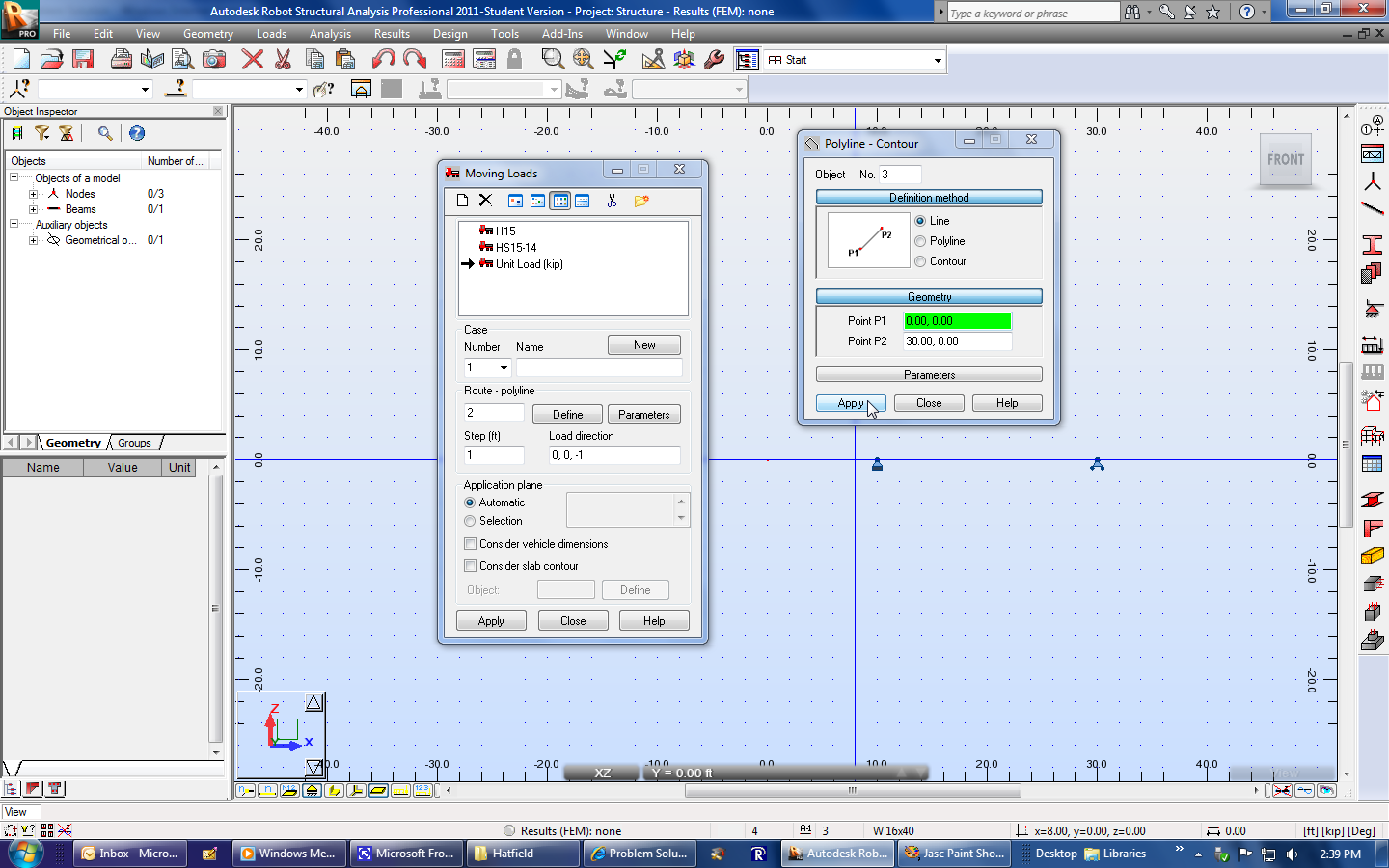 |
|
| Select Close. |  |
|
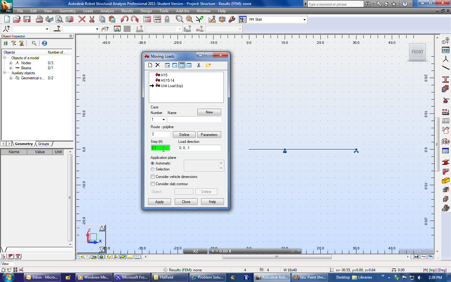
| Change the Step from "1" to "0.1". This will cause the influence line value to be calculated every 0.1 feet (or meters). | 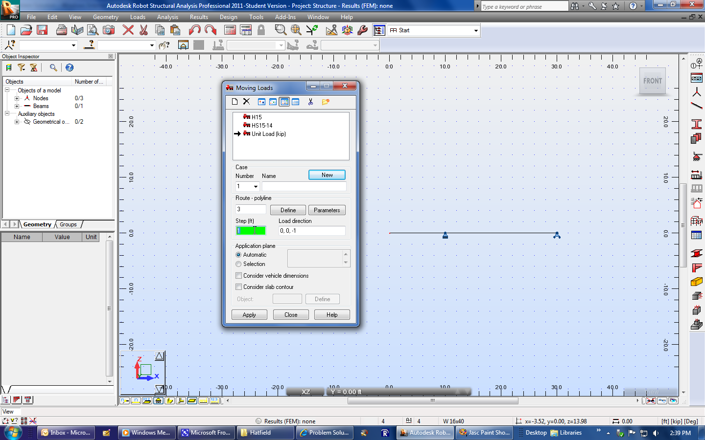 |
|
 |
||
| Select Apply. | 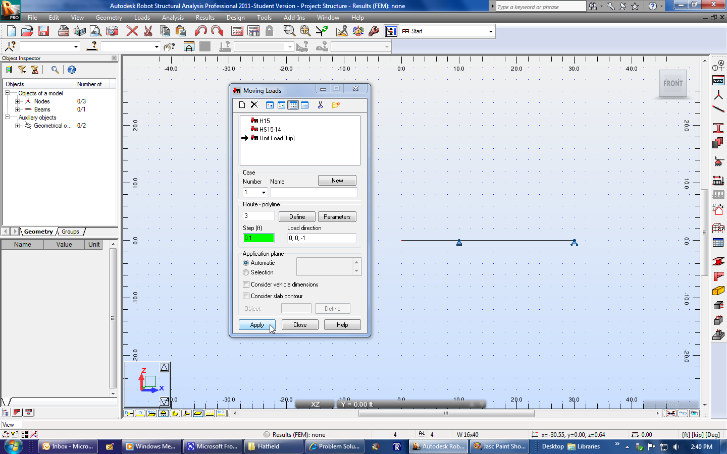 |
|
| The structure should now appear as a heavy green line. | 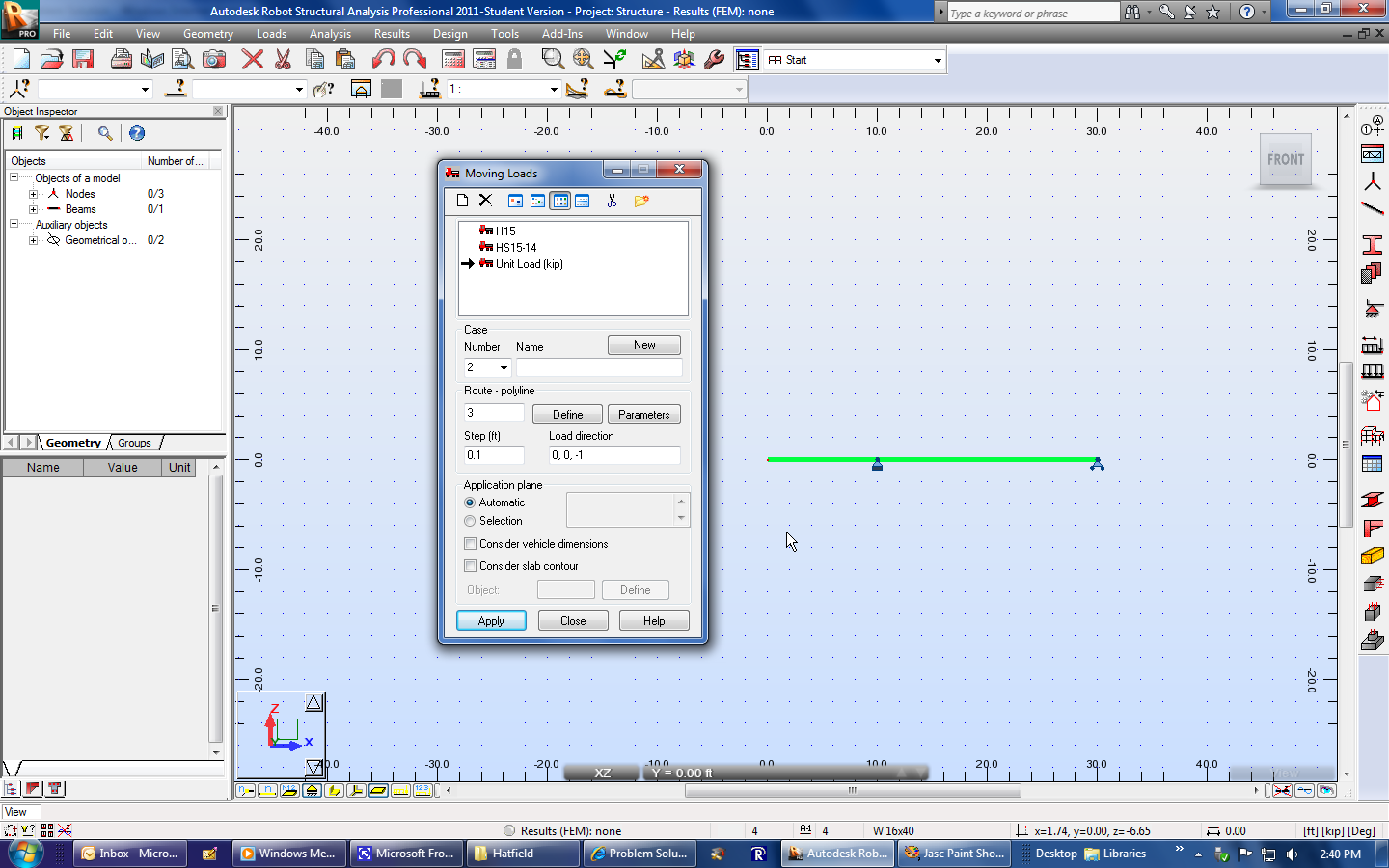 |
|
| Select Close. | 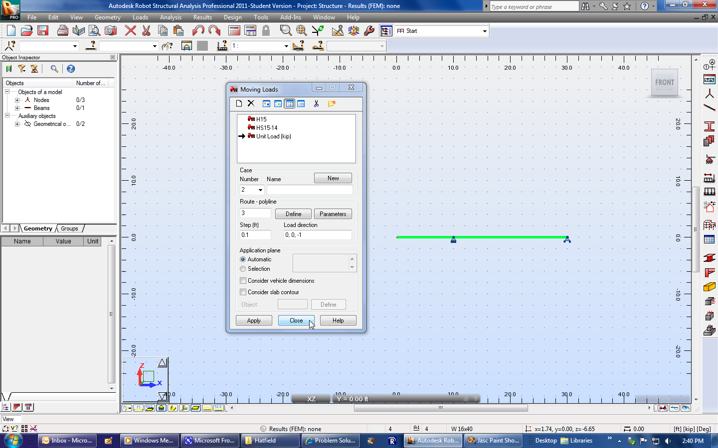 |
|
| Select Analysis, Calculations. | 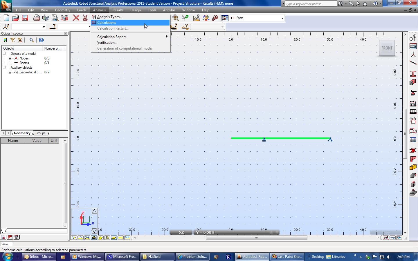 |
|
| Select Results, Advanced, Influence Line. | 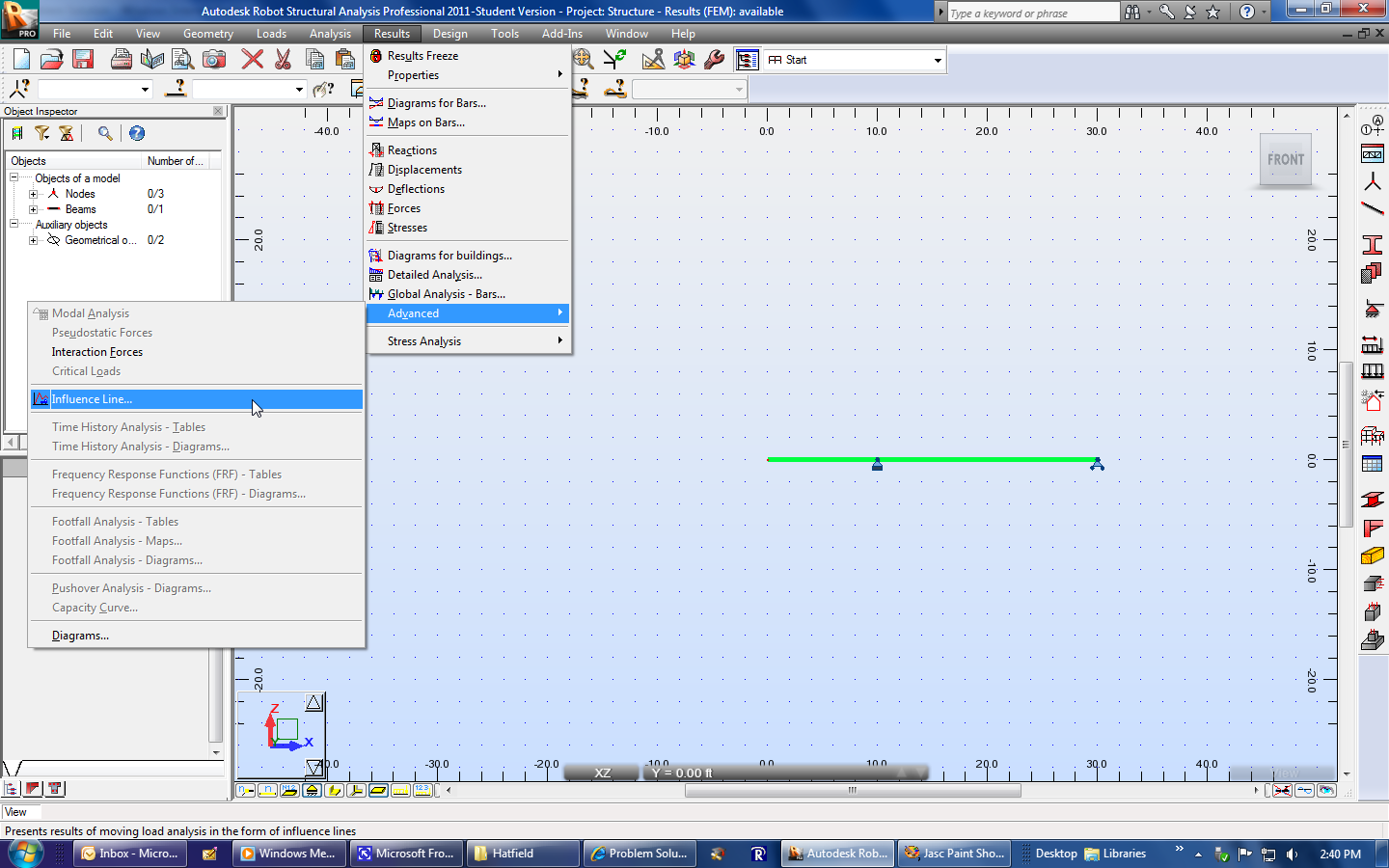 |
|
| The Influence Lines window will appear. | 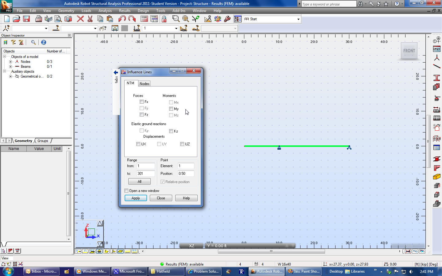 |
|
| Note that we are looking for the forces at B and C and the moment at C. | |
|
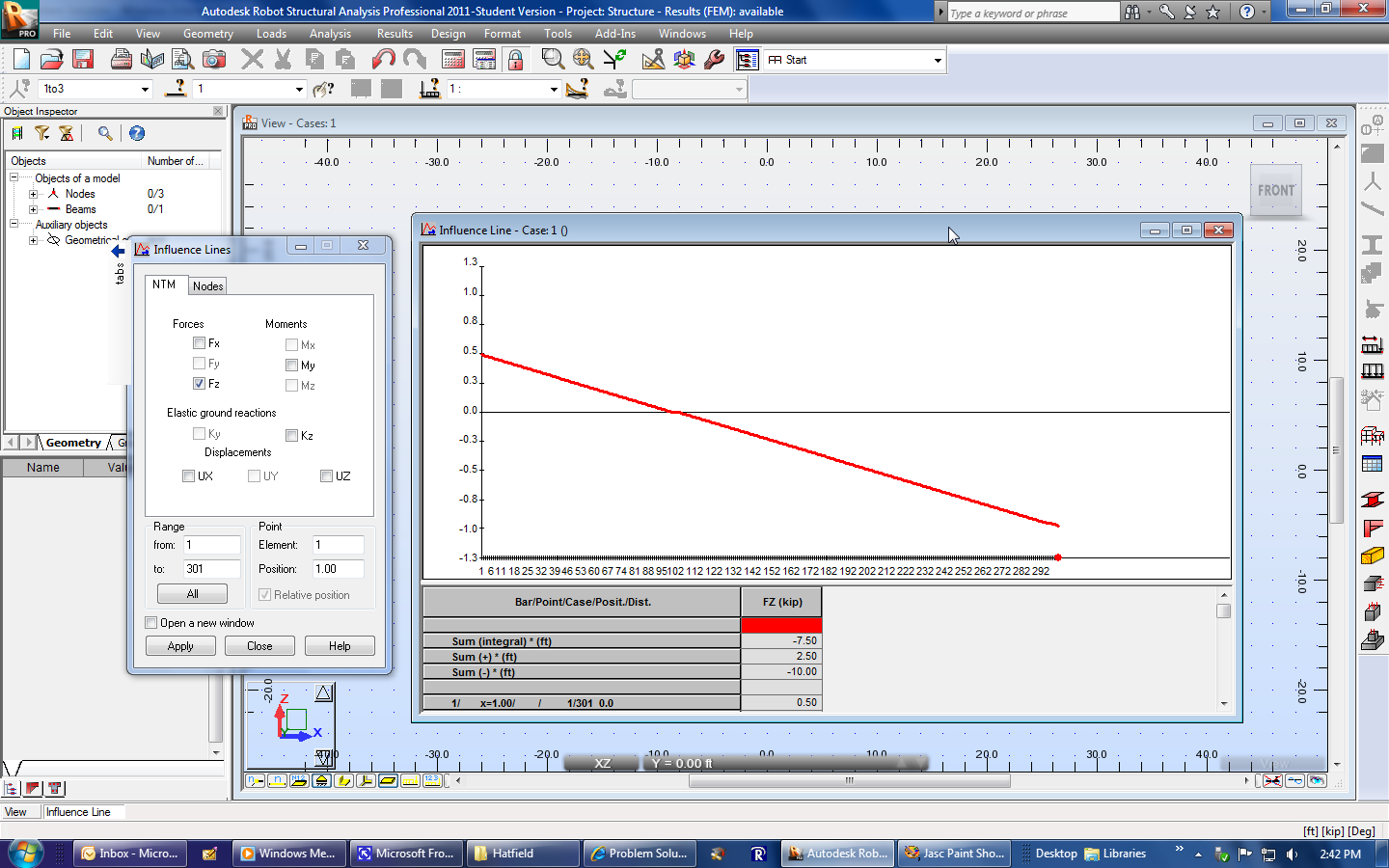
| Select Fz in order to create the influence line for the vertical force at B. | 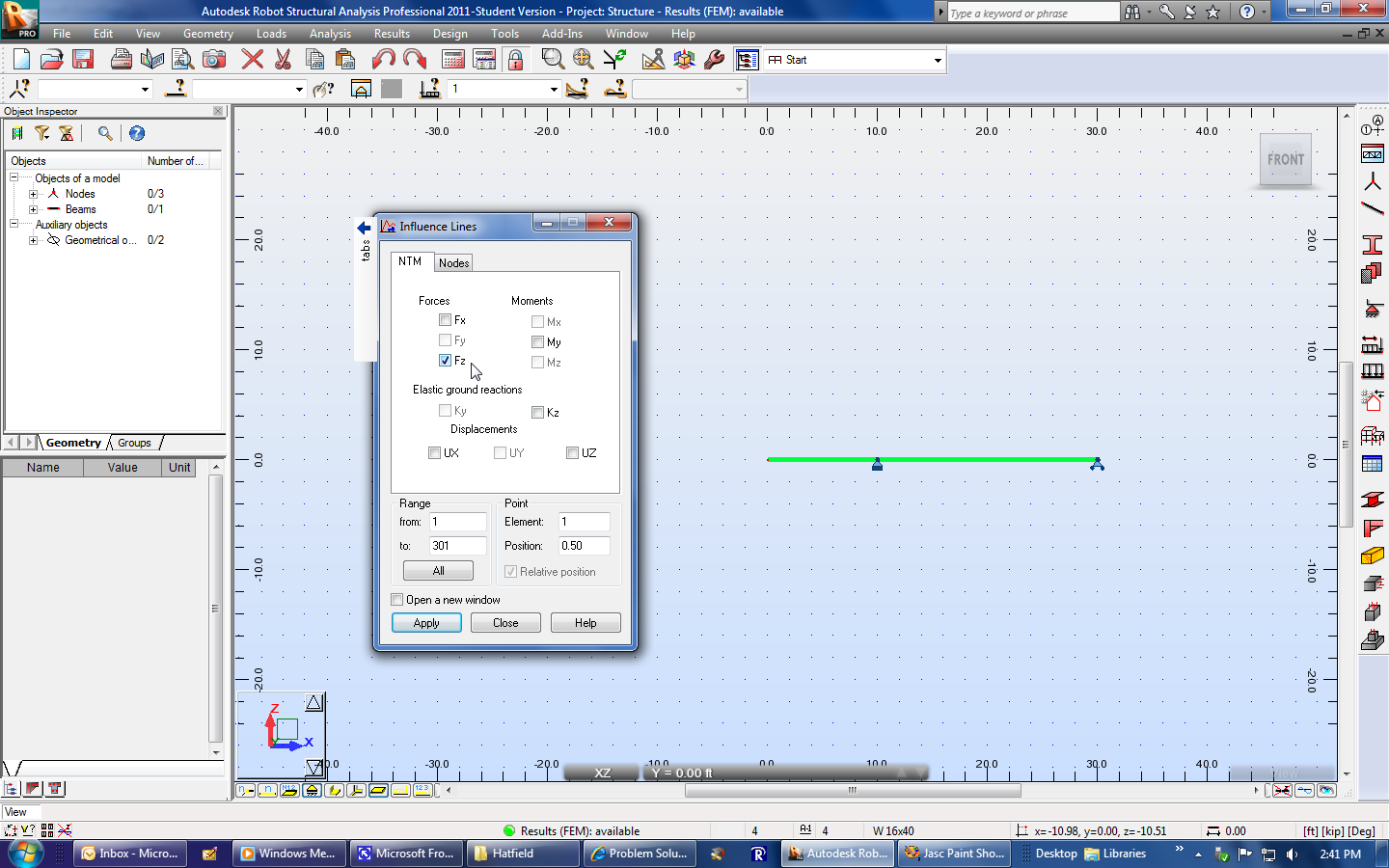 |
|
| Adjust the position from "0.50", which corresponds to the middle of the beam, to "1". This is equivalent to saying, "Point B is at 100% of the beam." | 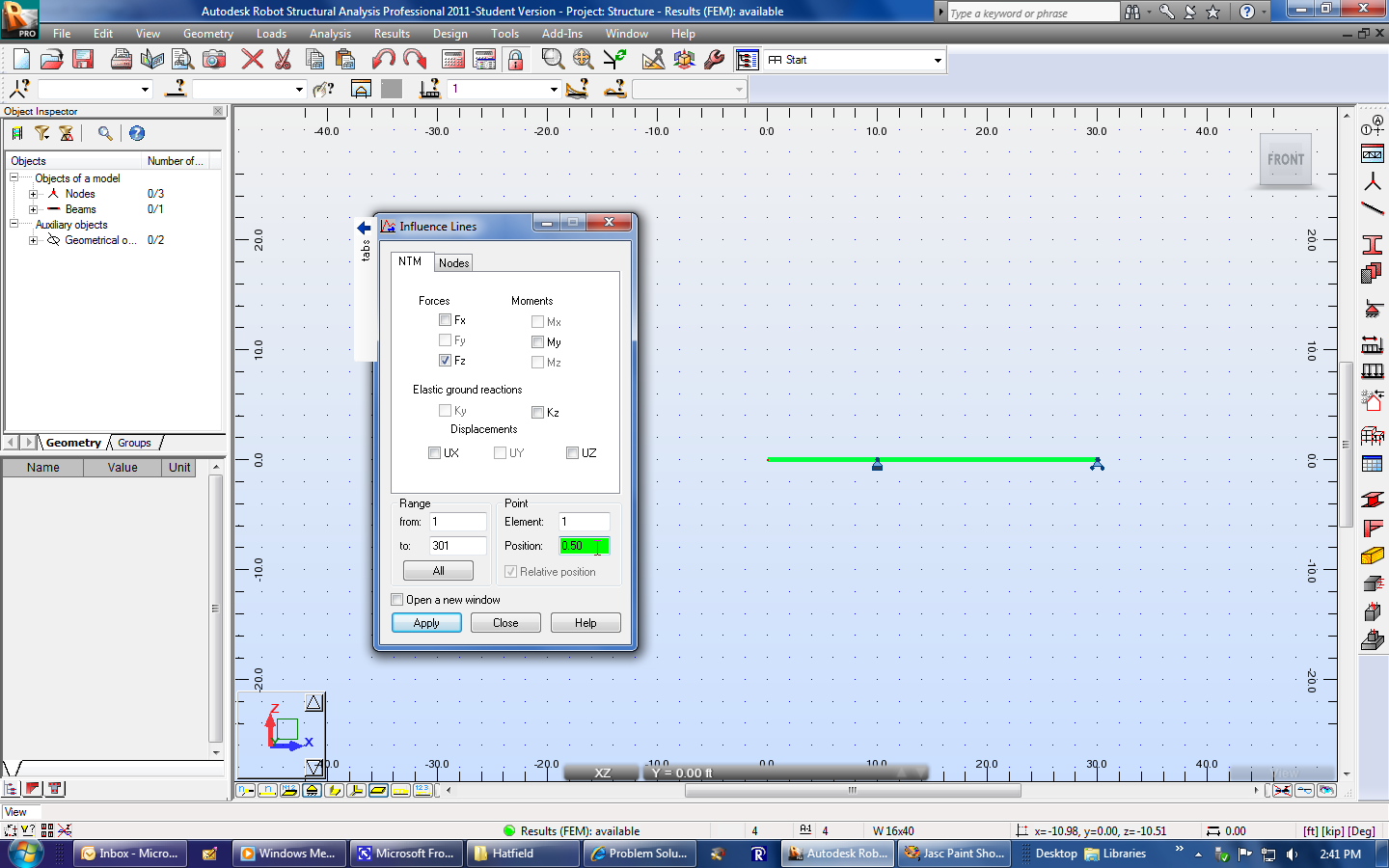 |
|
 |
||
| Select Apply. | 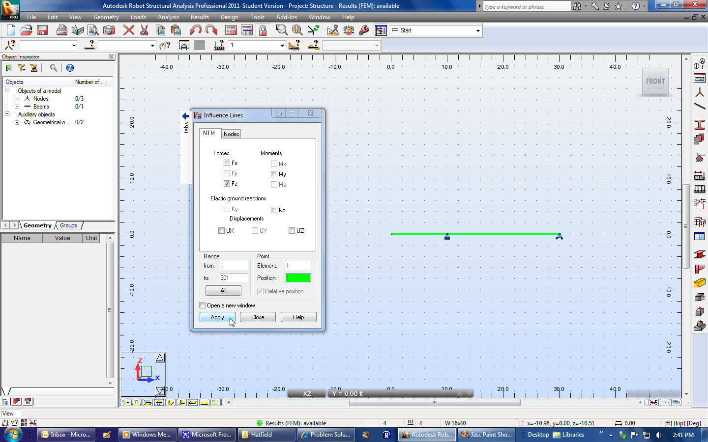 |
|
| Another window will appear. This shows the influence line for an internal shear force at point B. We were looking for an influence line for the reaction at B. These results have the same magnitude but opposite signs. I.e. the grounds sees an equal but opposite force to what the beam sees. | 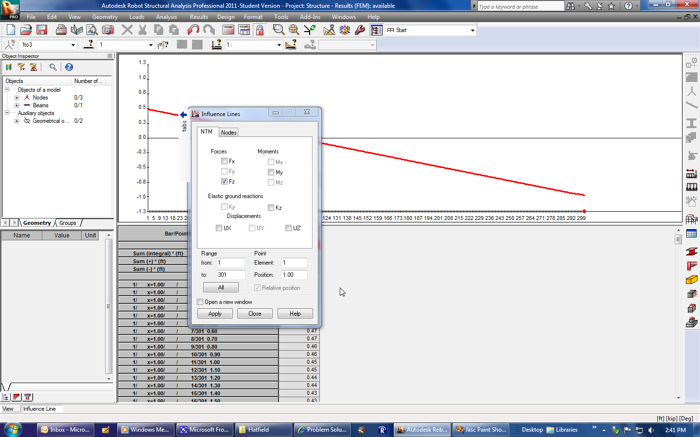 |
|
| Adjust the window position/size if desired. Note
that the model remains available in a window behind the
others.
Note the red dot on the horizontal axis. This shows the point in the beam where the graph is created. Also note the numbers on the horizontal axis. These correspond to the positions of the unit load as it progressed across the beam. The software calculated a result at each of these positions. Recall the step size of 0.1 feet. |
 |
|
| Adjust the position from "1" to "0.66" or "0.67". This will correspond to point C, which is 2/3 of the beam's length from the left end. | 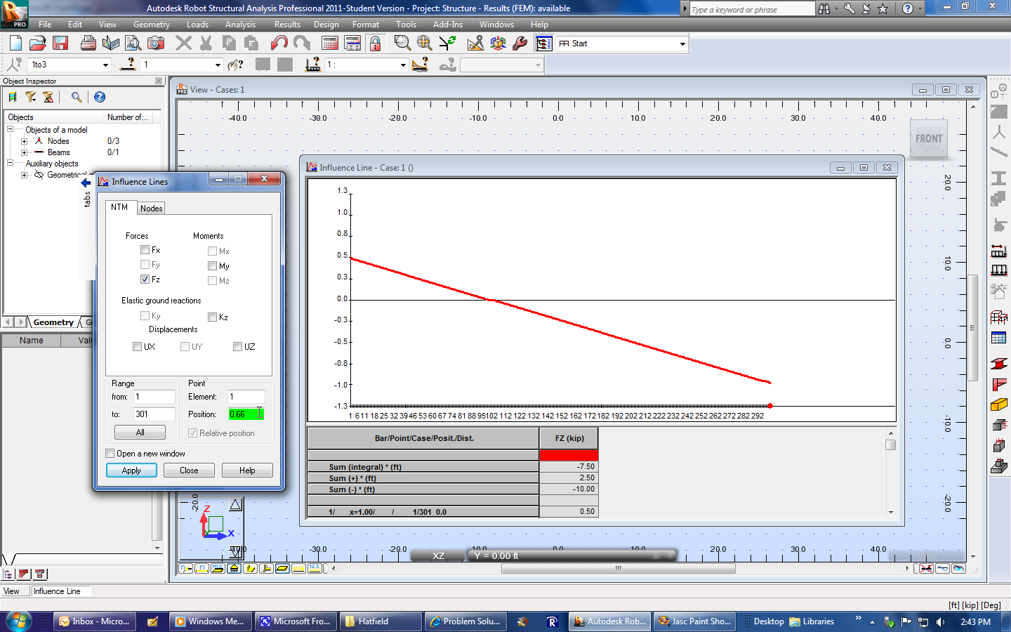 |
|
| Select Apply. | 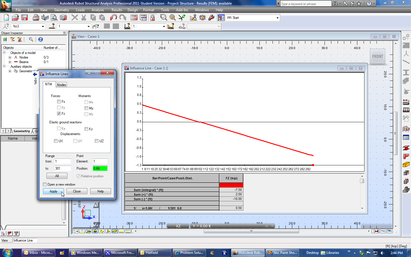 |
|
| This is the influence line for the internal shear force at point C. |  |
|
| Unselect Fz, and select My. | 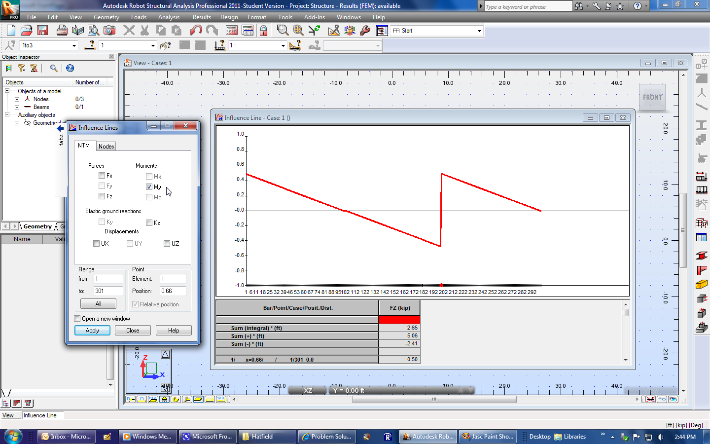 |
|
| Select Apply. | 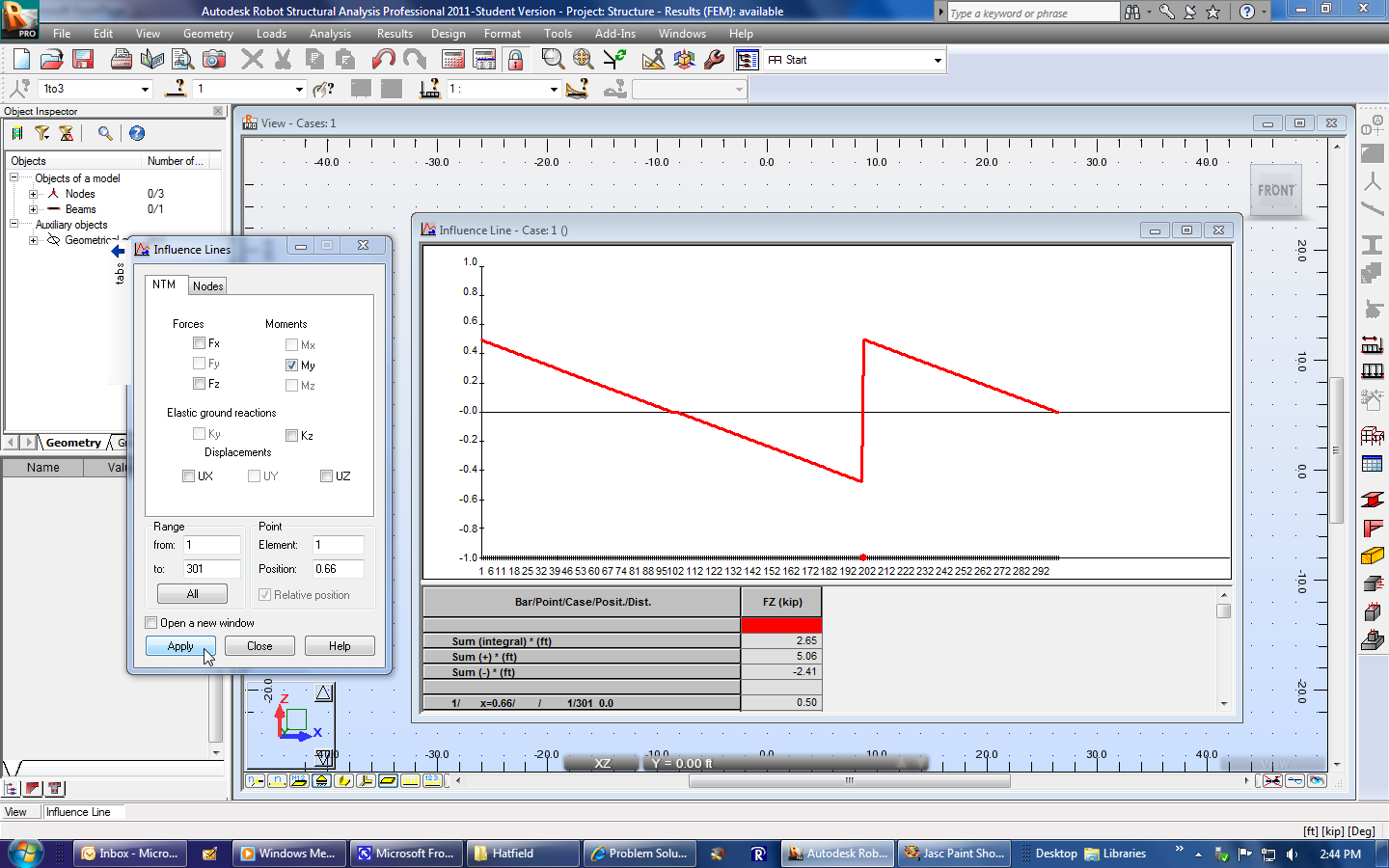 |
|
| This is the influence line for the internal bending moment at point C. |  |
|
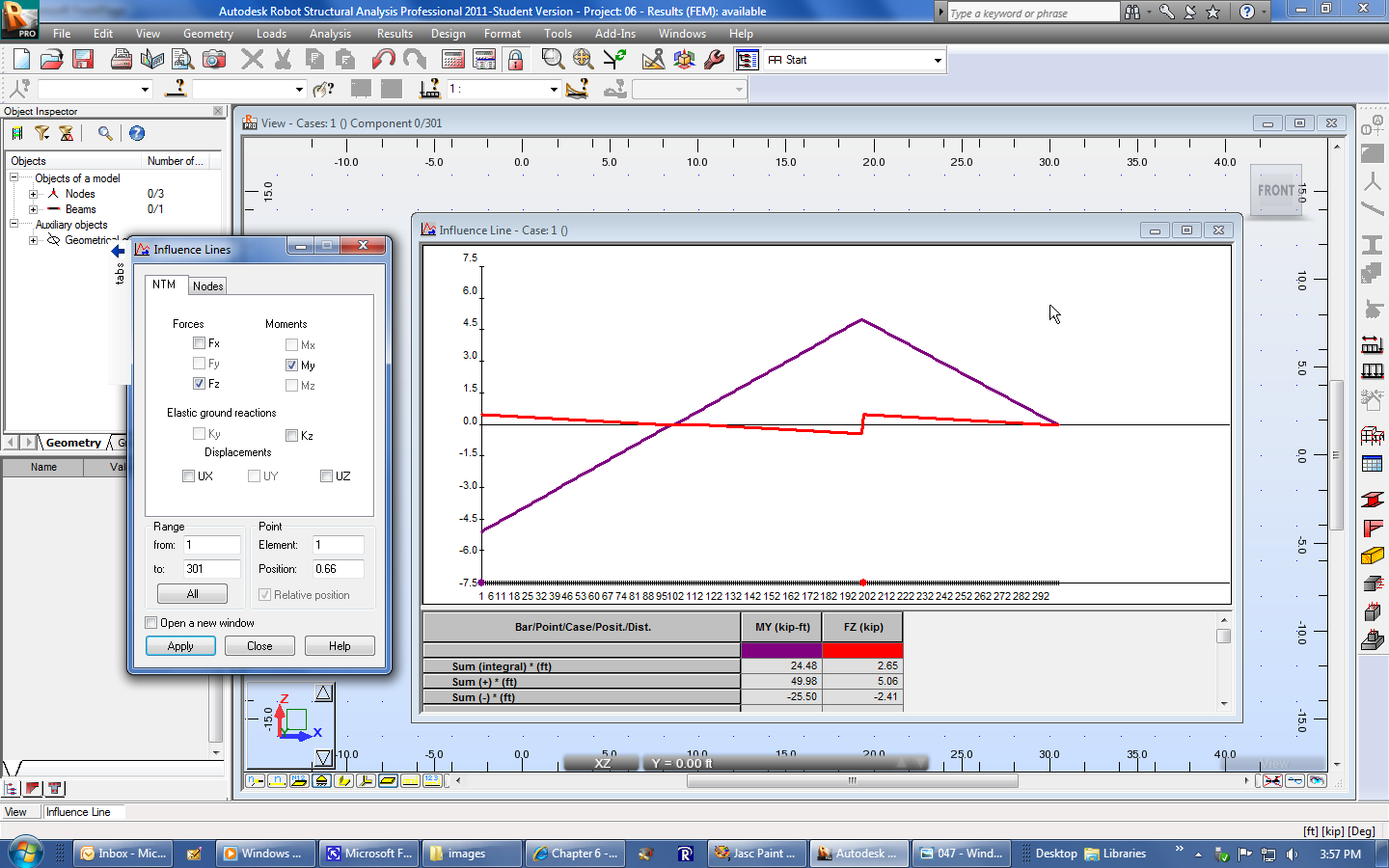
| Select Fz and My if you want to see both lines for point C on the same graph. |  |
|
| Select Apply. | 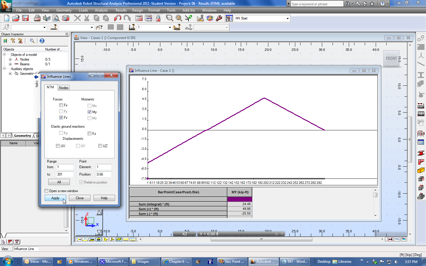 |
|
 |