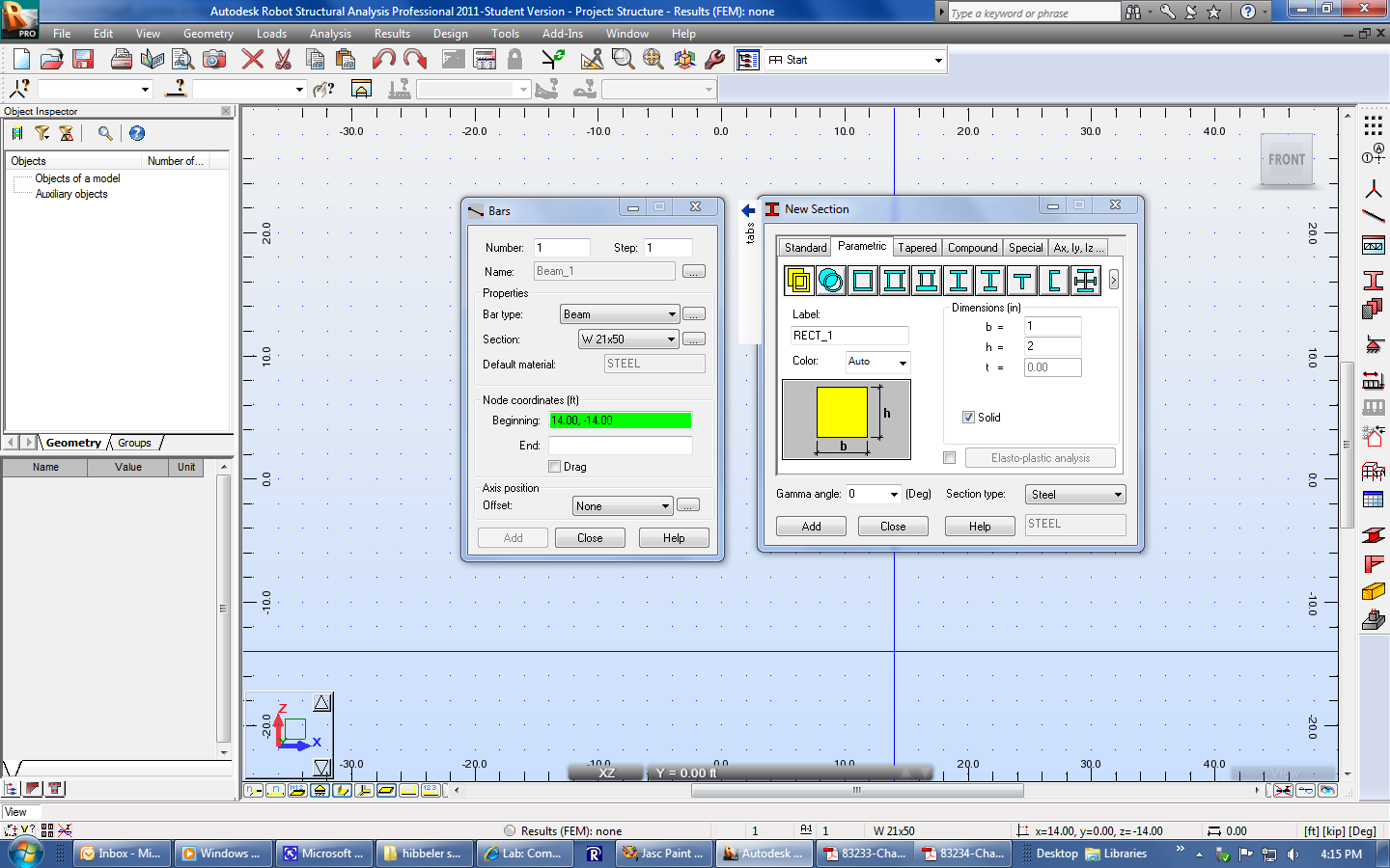
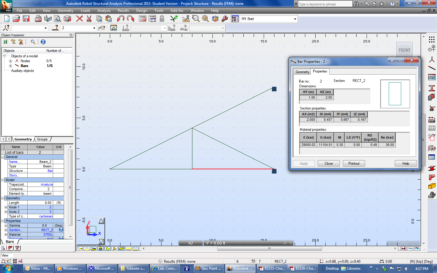
If your homework problem specifies a particular cross section area for the structural components, like problem 9-26, then you can define a solid rectangular cross section as you draw the structure. You can also verify the sizes by right-clicking on each bar, selecting Object Properties, and going to the Properties tab or using the Geometry information on the left hand side of the screen.
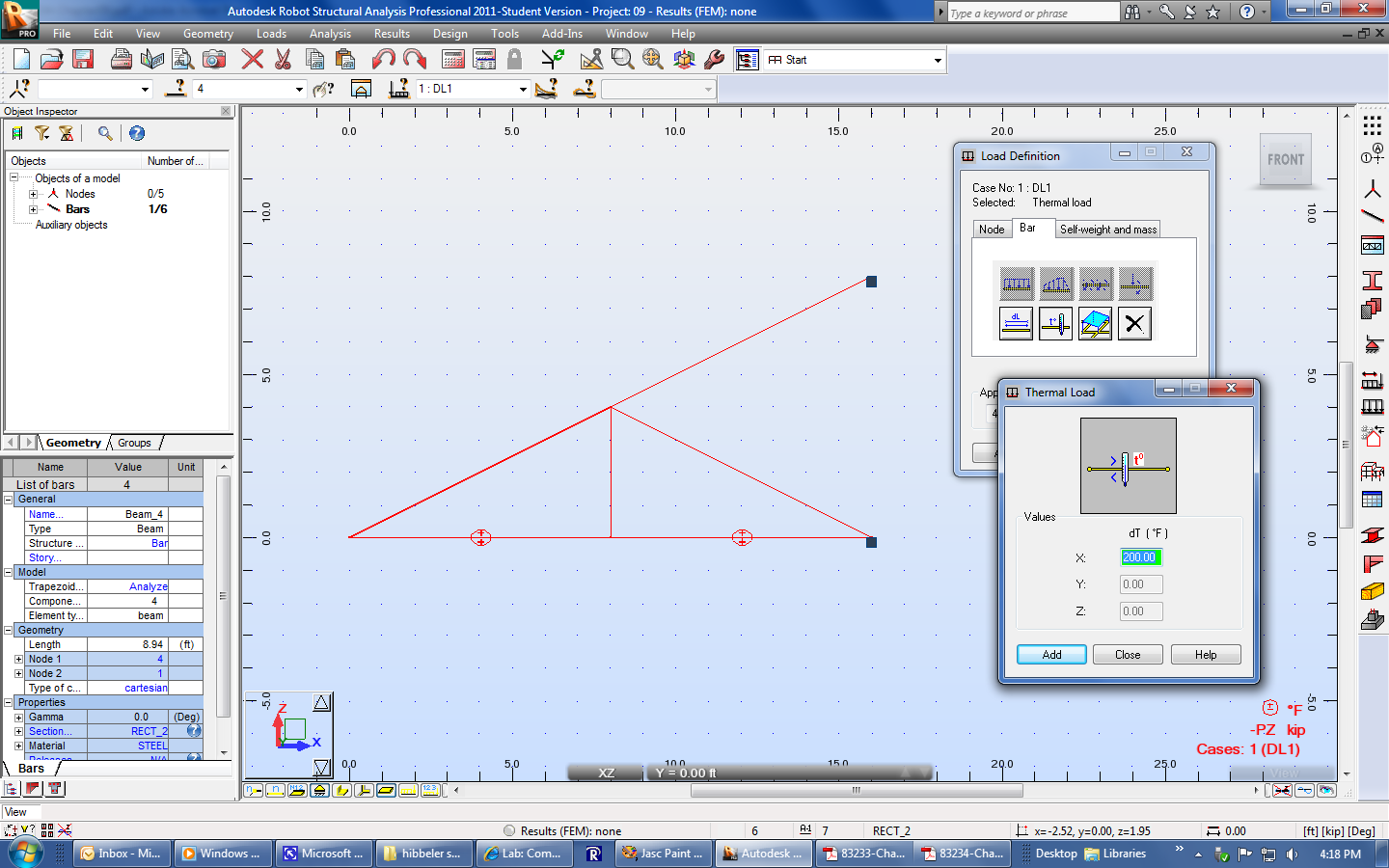
If your problem involves temperature change, like problem 9-28, you can use the Bar, Thermal Load option. Note the temperature symbol that appears on the selected bars.
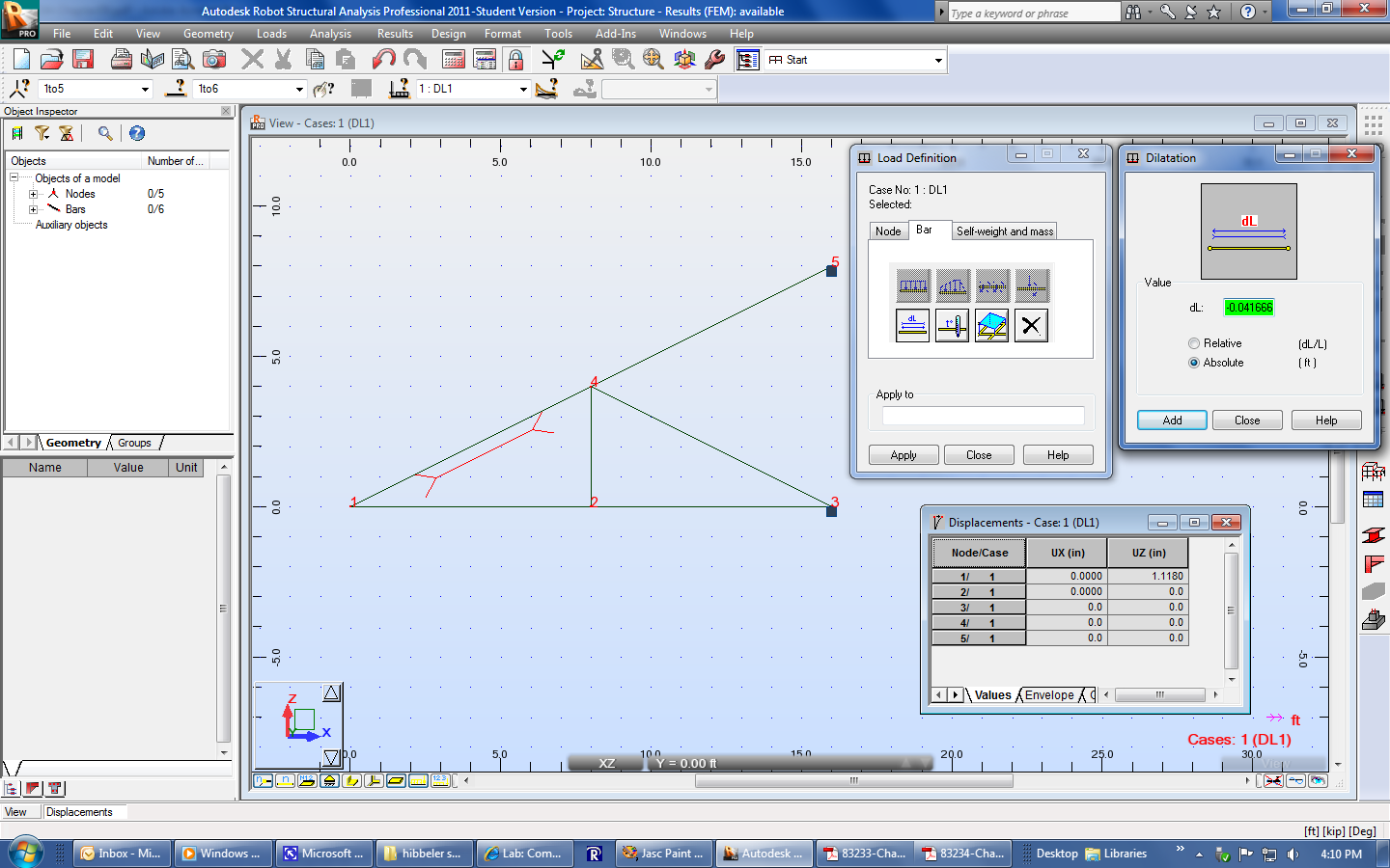
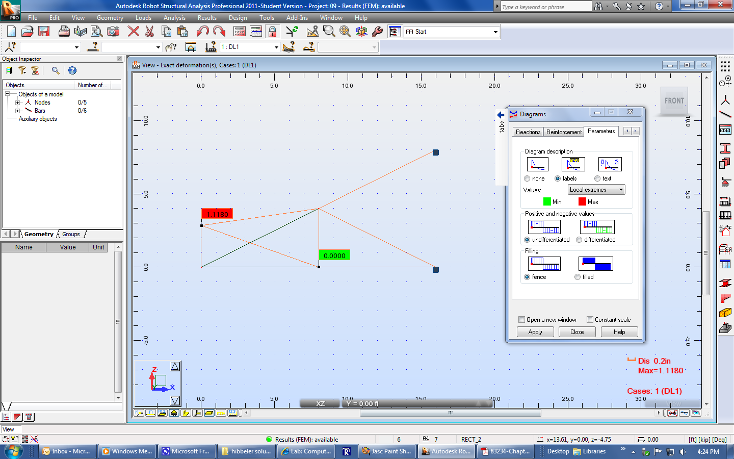
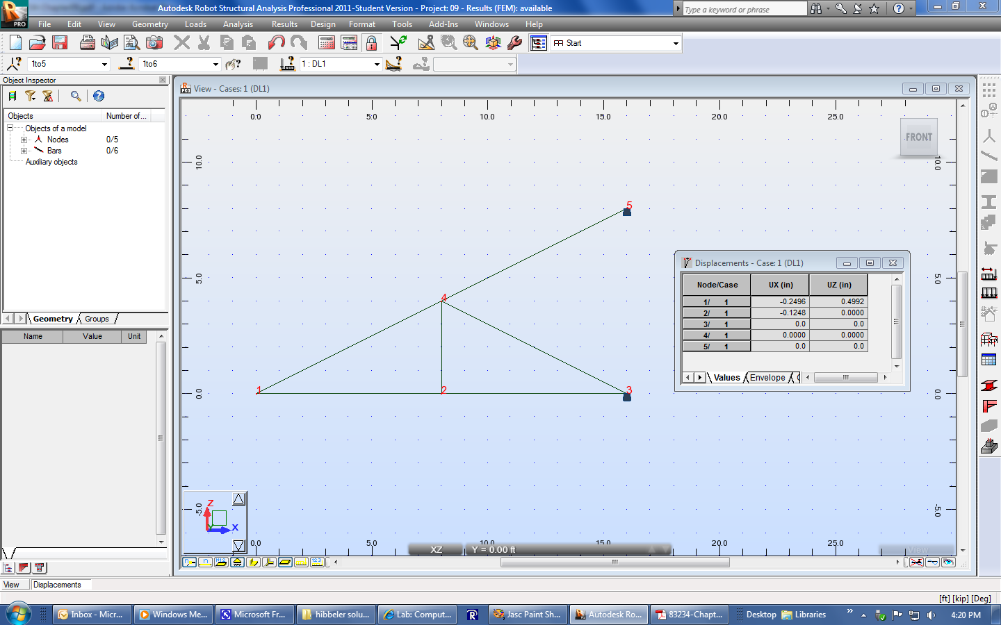
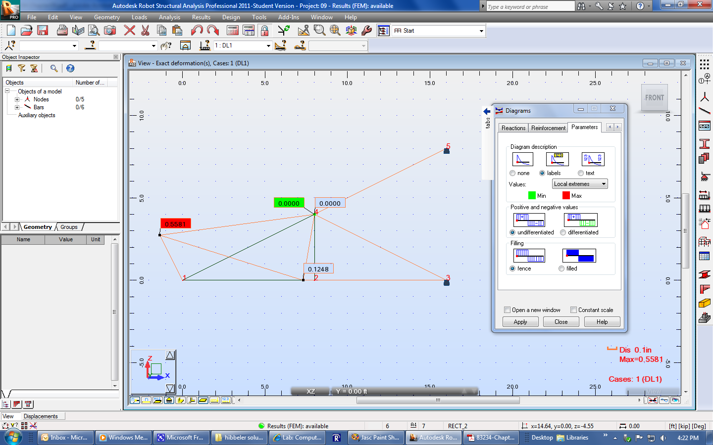
To compare Robot's deflection values to what you derived, you can go turn on the node numbers (first yellow button at the bottom of the screen) and go to Results, Displacements. Or you can go to Results, Diagrams for Bars and go to the Deformation tab. Select "Exact deformation for bars", go to the Parameters tab, select :"labels", and click Apply. This will show you a comparison of the undeformed and deformed structures, but the values may be diagonal distances. However, the homework problems usually ask for horizontal and/or vertical components, instead of diagonals.
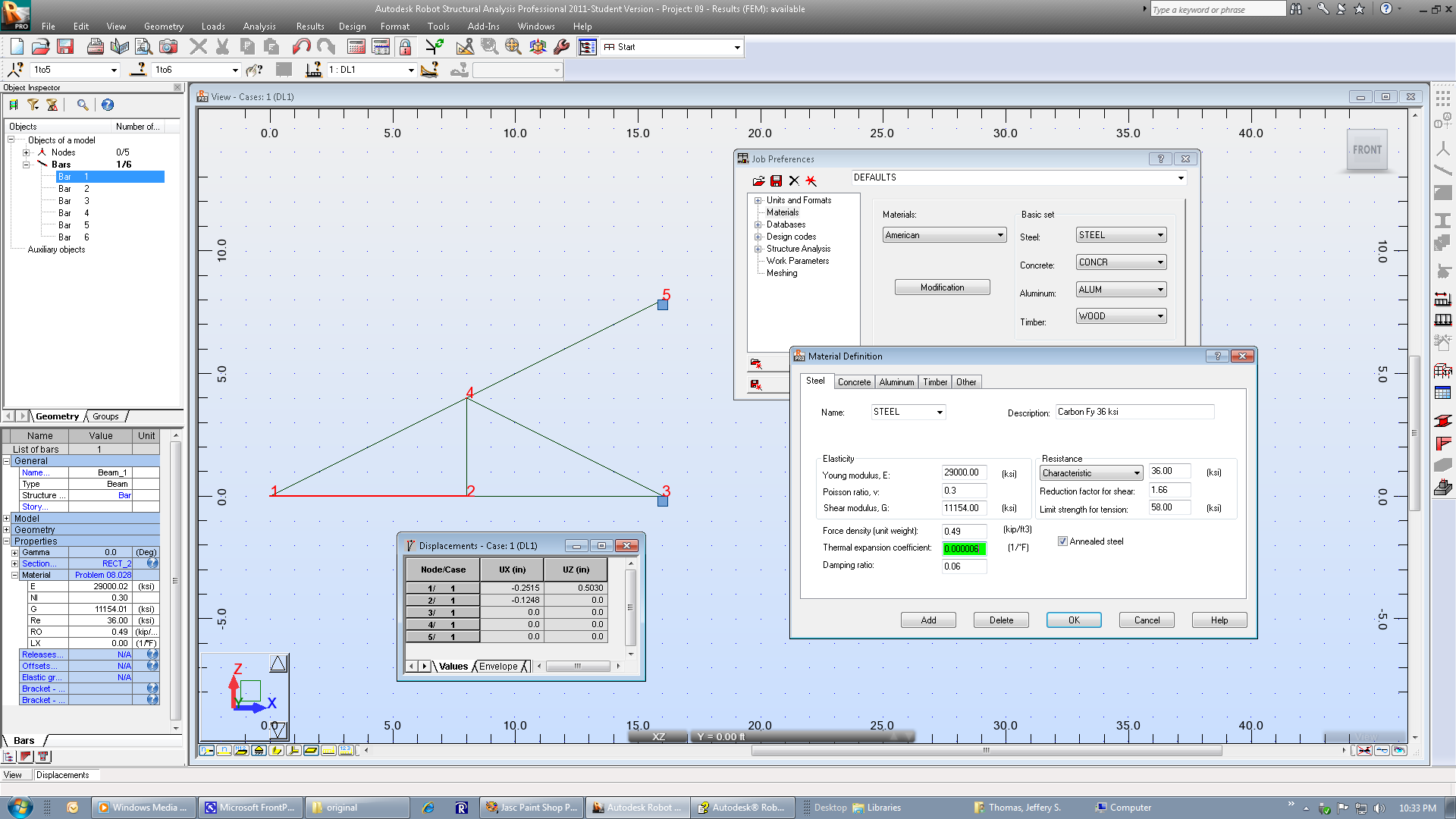
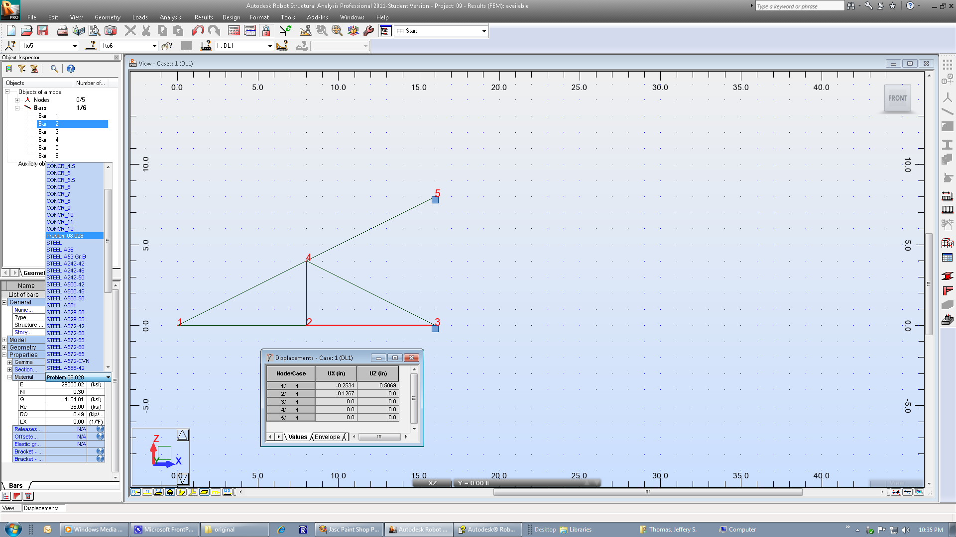
To edit a bar's coefficient of thermal expansion, click on the bar and go to Tools, Job Preferences. Select Modification. Give the material a new name, change the CTE value, and click Add. Click Ok on the Material Definition window and Ok on the Job Preferences window. To change any other bar's material to your newly defined material, click on it and use the Geometry area on the left hand side of the screen.
If your problem involves fabrication errors, like problem 9-29, you can use the Bar, Dilatation option. Watch for feet and inch conversions, and note the dilatation symbol that appears next to the selected bar.