|
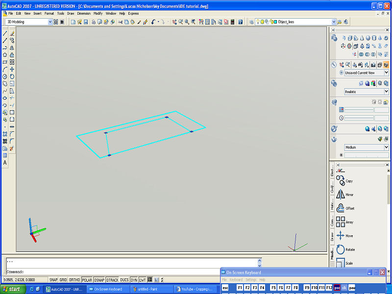
1. Select the REGION command icon in the DRAW toolbar.
2. In the command prompt area, the message "select objects:" is displayed. Select the polygon we just edited. 3. Inside the graphics window, right-mouse-click to accept the selection and create a region. 4. Inside the graphics window, click once with the right-mouse-button, to bring up the popup option menu.
|
 |
|
|
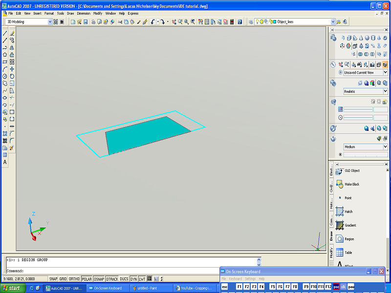
5. Pick REPEAT REGION, with the left-mouse-button, in the popup menu to
repeat the last command.
6. In the command prompt area, the message "Select Objects:" is displayed. Select the rectangle by clicking on one of the edges. 7. Inside the graphics window, right-mouse-click to accept the selection and create a region. |
 |
|
|
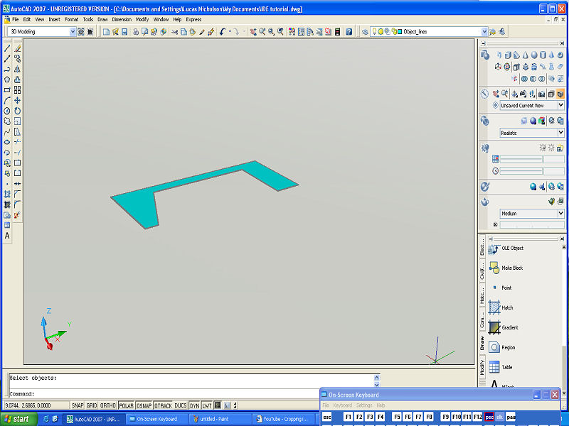
8. Move the cursor to the STANDARD toolbar area and right-click on any
icon of the STANDARD toolbar to display a list of toolbar menu
groups.
9. Select MODELING, with the left-mouse-button, to display the MODELING toolbar on the screen 10. In the MODELING toolbar, click on the SUBTRACT icon. In the command prompt area, the message" subtract select solids and regions to subtract from…Select Objects:" is displayed. 11. Pick the rectangle by clicking on one of the edges. 12. Inside the graphics window, right-mouse-click to accept the selection and proceed with the SUBRTACT command. 13. In the command prompt area, the message "Select solids and regions to subtract…Select objects:" is displayed. Pick the four-sided polygon by clicking on one of the edges. 14. Inside the graphics window, right-mouse-click to accept the selection and proceed with the SUBTRACT command. |
 |
|
|
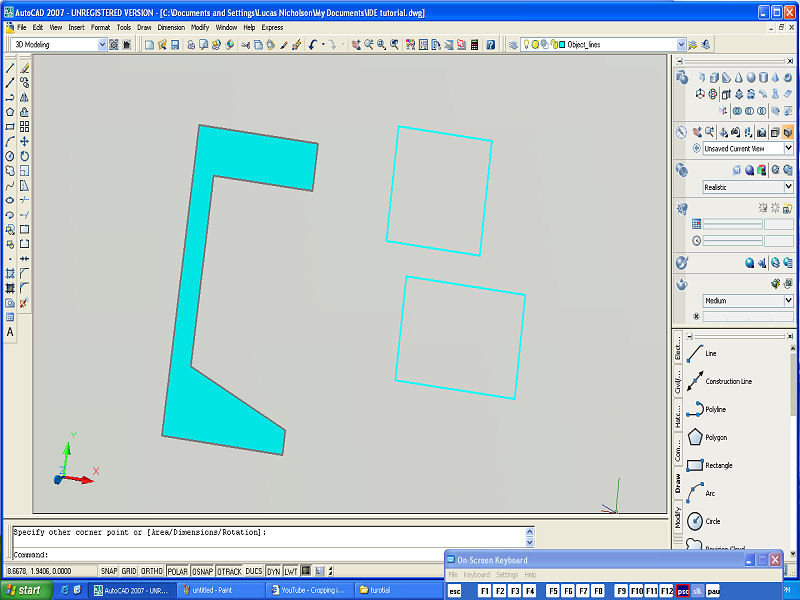
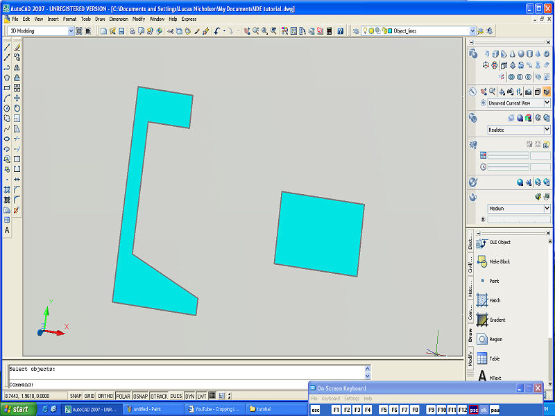
15. Select the RECTANGLE icon in the DRAW toolbar.
16. On your own, create two arbitrary rectangles roughly positioned as shown. We will use these two rectangles to shape the upper regions of the design. 17. On your own, convert the two rectangles into two REGIONS. 18. Select the MOVE icon in the DRAW toolbar. 19. In the command prompt area, the message "select objects:" is displayed. Pick one of the rectangles to move. 20. Inside the graphics window, right-mouse-click to accept the selection. 21. In the command prompt area, the message "specify base point or displacement:" is displayed. Pick the upper left corner of the selected rectangle. 22. Inside the graphics window, hold down the SHIFT key and right-mouse-click once to bring up the "Object Snap:" shortcut menu. 23. Select the FROM option in popup window. 24. Pick the upper left corner of the larger rectangle. 25. In the command prompt area, the message "Specify base point or
displacement: from base point: 26. On your own, perform the Boolean SUBTRACT operation to remove the small rectangle.
|
 |
|
|
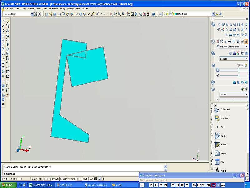
27. Select the ROTATE icon in the MODIFY toolbar.
28. In the command prompt area, the message "Select Objects:" is displayed. Pick the rectangle to rotate. 29. Inside the graphics window, right-mouse-click to accept the selection. 30. In the command prompt area, the message "Specify base point or displacement:" is displayed. Pick the upper inside corner of the 2D sketch. 31. Inside the graphics window, hold down the SHIFT key and right-mouse-click once to bring up the OBJECT SNAP shortcut menu. 32. Select the FROM option in popup window. 33. Pick the upper right corner of the 2D sketch. 34. At the command prompt: @0,-0.125 ENTER 35. Select the MOVE icon in the DRAW toolbar.
|
 |
|
|
36. In the command prompt area, the message "Select Objects:" is
displayed. Pick the rotated rectangle to move.
37. Inside the graphics window, right-mouse-click to accept the selection. 38. In the command prompt area, the message "Specify base point or displacement:" is displayed. Pick the upper left corner of the selected rectangle. 39. In the command prompt area, the message "Specify base point or displacement:" is displayed. Pick the upper inside corner of the 2D sketch.
|
 |
|
| 40. On your own perform the Boolean SUBTRACT operation as before and complete the 2D sketch. | 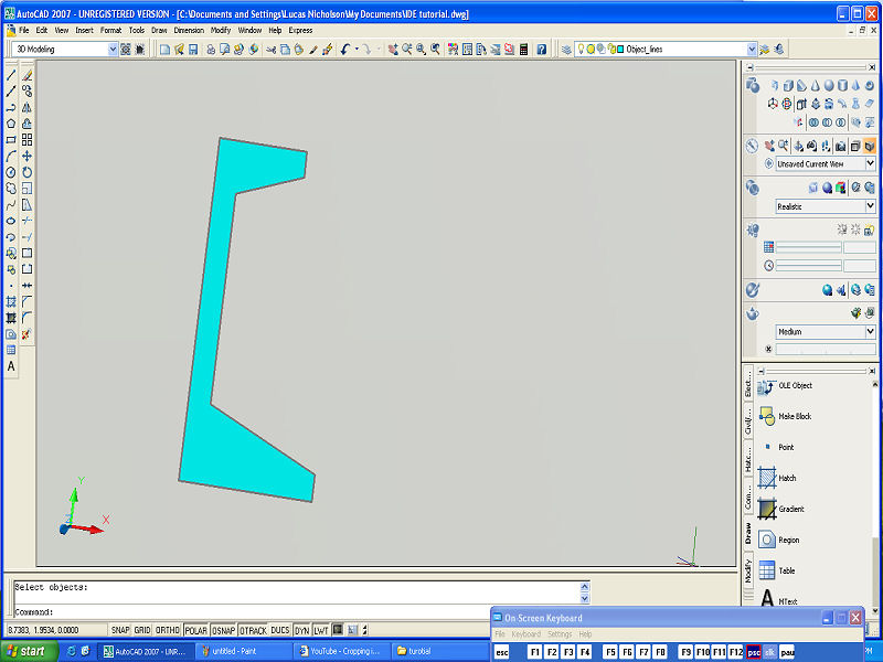 |
|
|
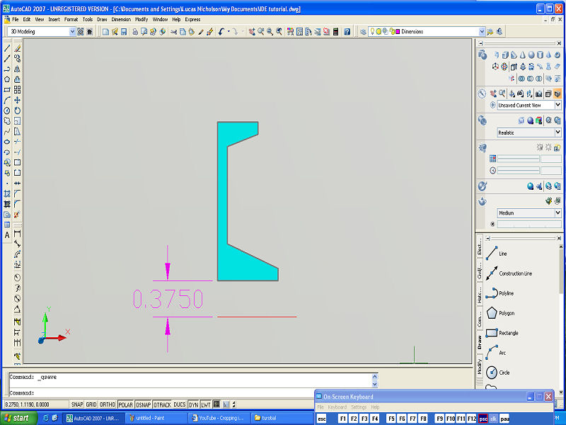
41. On your own, create a centerline that is 3/8 below the 2D sketch as
shown. This line will be used as the axis of rotation for the
revolved feature. (Trim the line so that the left endpoint is
aligned to the left edge of the 2D sketch.)
|
 |