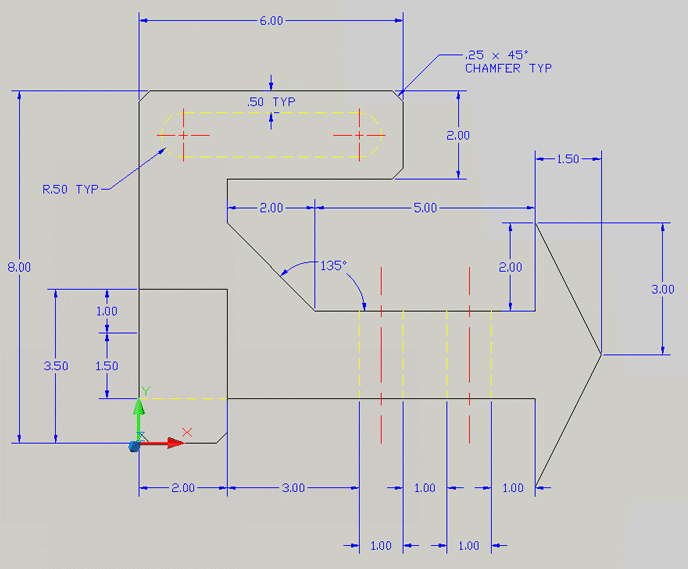
Dimensions explain:
- size of the object
- location of features (e.g. hole)
- characteristics of features (e.g. diameter and depth)
- tolerance (or accuracy)

Dimensions explain:
- size of the object
- location of features (e.g. hole)
- characteristics of features (e.g. diameter and depth)
- tolerance (or accuracy)
Terminology
- Dimension Text – numerical value on drawing that defines size
- Dimension Line – thin, solid line; shows extent and direction of dimension
- Arrowheads – placed at ends of dimension lines; shows limits of dimension
- Extension Line – thin, solid line perpendicular to dimension line; indicates which feature is associated with dimension
- Leader Line – thin, solid line; used to indicate features associated with note, dimension or symbol
- Tolerance – amount a particular dimension is allowed to vary; all dimensions have them
Standards
- American National Standards Institute, ANSI
- ANSI Y14.5 is widely used in the United States.
- British Standards Institution, BSI
- Deutsche Industries-Normen, DIN
Guidelines
The main goal for dimensioning is to provide clarity.Do
- Do not over-define or under-define the object.
- If you want to include unnecessary dimensions for reference, place them in parentheses (XX).
- Keep dimensions on a separate layer.
- The size and style of leader lines, text, and arrows should be consistent throughout the drawing.
- Use OSNAP to select the features to be dimensioned.
- AutoCAD uses the DEFPOINTS layer for the small points at the end of an extension line. This layer will not print.
Do not
- place dimensions in the view that best describes the feature
- use linear dimensions for cylinders, cones and frustums
- use diameter dimensions for holes
- use f for circles
- use R for arcs
- position dimensions between views
- place as many dimensions in one view as possible
- evenly space dimensions -- away from the object's edge and from other dimensions
- display only the number of decimal places required for manufacturing precision
- assume square corners and symmetry, unless otherwise noted
- put dimensions inside the object
- overlap dimensions
- dimension to hidden lines
References
- feh.eng.ohio-state.edu/Lectures/191au05/18 H191 W05 D03 1-1 V1.2 - Introduction to Dimensioning.ppt
- courses.washington.edu/mengr123/current/Dimension%20Rules.pdf#search=%22dimensioning%20rules%22
- courses.washington.edu/mengr123/current/Dimensions.pdf#search=%22dimensioning%20guidelines%22
- www.we-r-here.com/cad/tutorials/level_4/4-11.htm
Shorthand
- 2X Ø12 -- Two holes with diameter 12 and depth of 30
- R20 TYP– Radius 20 –Typical
- 36 – square dimension of 36
- Ø8 Ø12 x 160º - Countersunk hole with diam.8 thru
- .25 – 20 UNC-2B – Thread note.