| Create a basic 2D rectangle using the line tool. You can use any dimensions you wish, just make sure that one of the corners of the rectangle is on the point 0,0. | 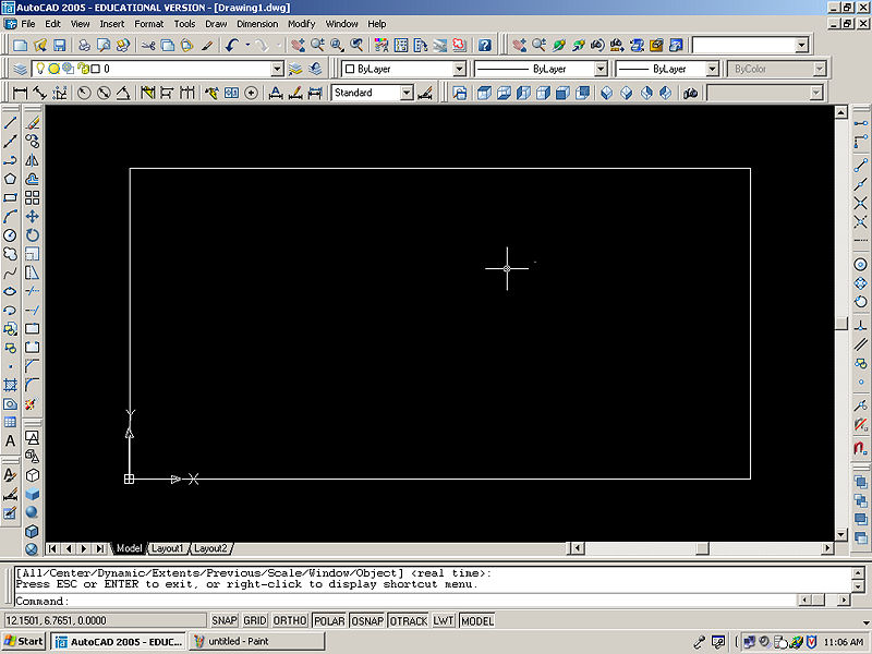 |
|
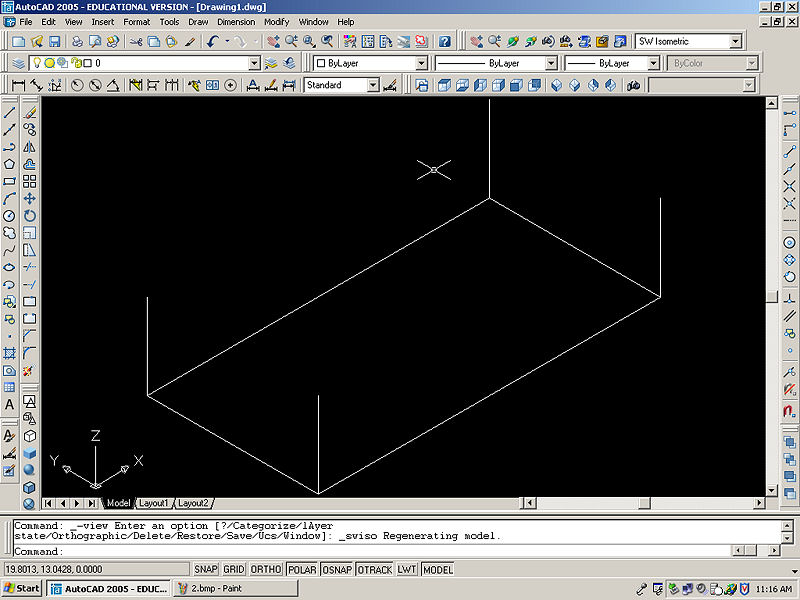
| When finished, click the SW Isometric View button on the View toolbar. This will show an angled view of your square. The Isometric views are very useful for working in 3D, and you should get familiar with them. While in an Isometric viewpoint, note the orientation of the UCS. The direction of the axes will be important later when inputting coordinates in 3D model space. | 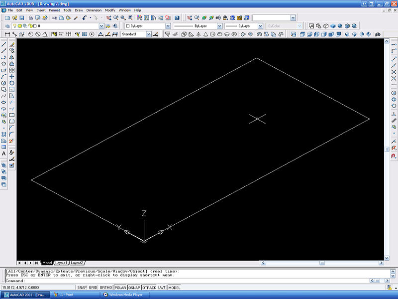 |
|
| Using the Line tool, start by clicking on any corner of the rectangle and dragging the curser upwards. This will begin the first step you take into creating the 3D object. Make sure AutoCAD is snapping the line into the axis. If it is not, you will think you are drawing in 3D because that is what your eye perceives, however you will just be drawing an angled line in 2D space. In the image to the right, you may think you are drawing the 3D line, as it appears in the left half, but really you could be drawing the right half of the image. | 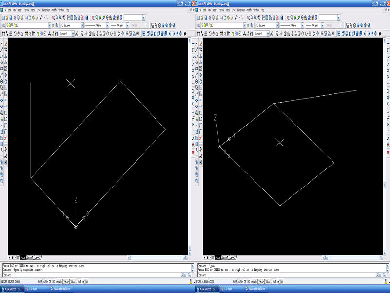 |
|
| Enter the Coordinates @0,0,5 this will be 0 in the x-axis, 0 in the y-axis, and 5 in the z-axis. Inputting the coordinates manually makes sure we are creating the line in the z-axis rather than the x- or y-axes. This is where it becomes important to pay attention to the UCS. As you change back and forth from different views, the UCS will be in different directions also. It is important to make sure you are creating lines in the correct orientation in relation to the UCS. | 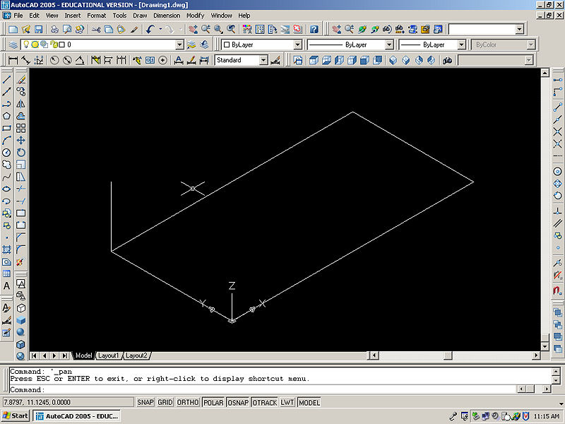 |
|
|
Repeat previous step for the other 3 corners of the box. Alternately, you can use a Copy With Base Point, and paste line onto the other 3 corners. If necessary click the SW Isometric View button to make sure that the entire drawing is within view. |
 |
|
| Use the line tool to connect the top corners of the box. You have successfully created the wire frame for a 3D box. | 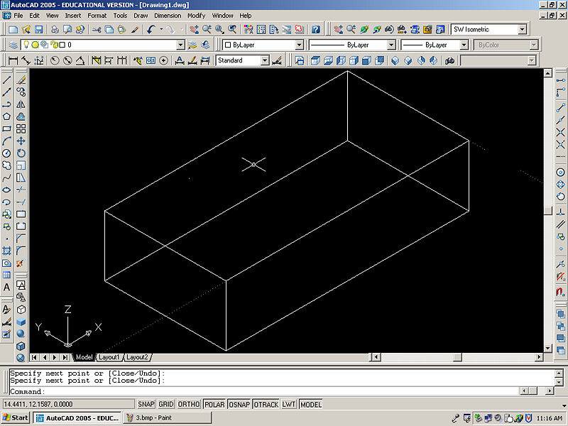 |