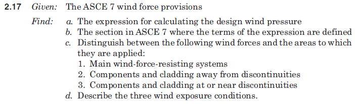
Design wind pressure: ASCE 7 section 6.4.2
ASCE 7 sections
6.1 general
6.2 definitions
6.3 symbols and notation
6.4 method 1 - simplified procedure
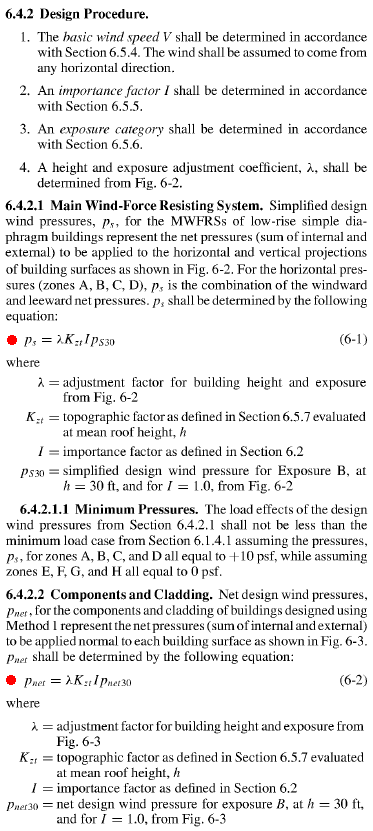
6.4.2 design procedure
6.4.2.1 main wind-force resisting system
6.4.2.2 components and cladding
6.5 method 2 - analytical procedure
6.6 method 3 - wind tunnel procedure
| Category | Zones (see figures 6-2 and 6-3) |
Formula | Areas | |
| main wind-force-resisting systems (diaphragms, shearwalls) | A-D. horizontal E-H. vertical |
ps | projected vertical or horizontal surface areas of the overall structure | |
| components and cladding (individual structural components) | away from discontinuities | 1. roof interior 4. wall interior |
pnet | surface areas that are tributary to the specified structural component |
| at or near discontinuities (corners of walls, roof ridges, roof eaves, gable ends, and roof overhangs) | 2. roof ends 3. roof corners 5. wall ends |
|||
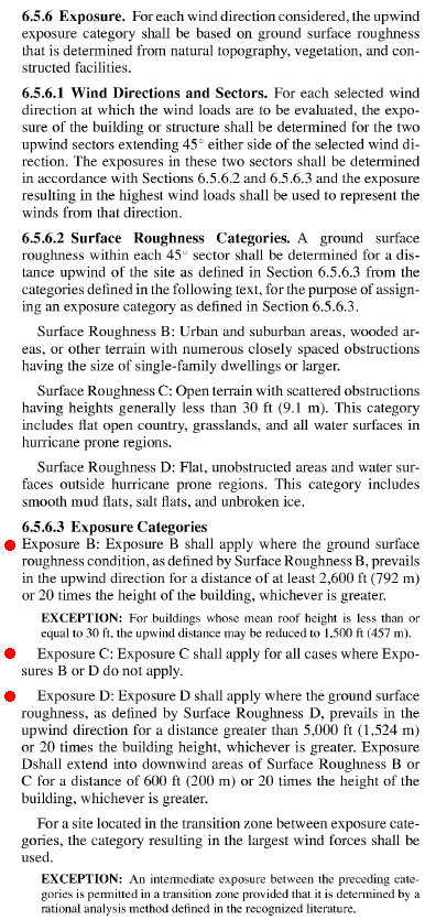
Wind exposure conditions: ASCE 7 section 6.5.6