Given
closely spaced floor beams
Load D = 18 psf
L = 50 psfLoad combination D+L (ASD)
1.2D+1.6L (LRFD)Span L = 14 ft Member spacing Tributary width = b = 16 in. OC
wD = 18 lb/ft2 (1 ft/12 in.)2 x 16 in. = 2 lb/in.
wL = 50 psf (1 ft/12 in.)2 x 16 in. = 5.556 lb/in.Stress grade and species No. 1 Hem-Fir Unbraced length lu = 0 Moisture content MC ≤ 19% Live load deflection limit Allow. ΔL ≤ L/360 = 0.4667 in.
Allow. ΔD+L ≤ L/240 = 0.7000 in.Dry-service conditions Normal temperatures Bending about strong axis
Trial Size
Fb = 975 psi (NDS Supplement table 4A)
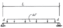
vertical ground reactions: wL/2
Vmax = +/- wL/2
Mmax = wL2/8S ≥ Mmax/Fb = (7.556 lb/in.) x (14 ft x 12 in./ft)2 / (8 x 975 lb/in.2) = 27.34 in.3
S2x10 = 21.39 in.3 ✘ (NDS Supplement table 1B)
S2x12 = 31.64 in.3 ✓ (NDS Supplement table 1B)
Size Category (NDS Supplement tables 1A and 1B)
dimension lumber
dressed size: 1.5" x 11.25"
A = 16.88 in.2
Sxx = 31.64 in.3
Ixx = 178.0 in.4
Reference Design Values (NDS Supplement table 4A)
Fb = 975 psi
Fv = 150 psi
E = 1,500,000 psi
Adjusted ASD Values: F'b, F'v , E'
NDS Supplement table 4A Cr = 1.15
CM = 1
Cfu = 1
CF = 1NDS Supplement section 2.3
CD = 1 (L)
Ct = 1NDS Supplement section 3.3 CL = 1 (lu = 0)
NDS Supplement section 3.7
CP = 1 (not a column)
NDS Supplement section 3.10
Cb = 1 (not enough info given)
NDS Supplement section 4.3 Ci = 1
NDS Supplement section 4.4
CT = 1 (not a truss)
Property Reference Design
Values (psi)
(Table 4A)Adjustment Factors (Table 4.3.1) Adjusted Design
Values (psi)CD CM Ct CL CF Cfu Cr CP Ci CT Cb bending stress Fb 975 1 1 1 1 1 1 1.15 1 1,121 tension stress parallel to grain Ft 625 1 1 1 1 1 -- shear stress parallel to grain Fv 150 1 1 1 1 150 compression stress perpendicular to grain Fc⊥ 405 1 1 1 1 -- compression stress parallel to grain Fc 1,350 1 1 1 1 1 1 -- modulus of elasticity (or MOE) E 1,500,000 1 1 1 1,500,000 modulus of elasticity for stability calculations Emin 550,000 1 1 1 1 --
Actual Stresses (ASD) and Deflection
vertical ground reactions: wL/2
Vmax = +/- wL/2
Mmax = wL2/8fb = M/S = (7.556 lb/in.) x (14 ft x 12 in./ft)2 / (8 x 31.64 in.3) = 842.5 psi
fv = 1.5V/A = 1.5 (7.556 lb/in. x 14 ft x 12 in./ft) / (2 x 16.88 in.2) = 56.40 psi
Reduced Shear (NDS section 3.4.3)
fv reduced = 1.5 (7.556 lb/in. x (14 ft x 12 in./ft - 2 x 11.25 in.)) / (2 x 16.88 in.2) = 48.85 psiSee formula 11 for the deflection.
ΔL = 5(5.556 lb/in.)(14 ft x 12 in./ft)4 / 384(1,500,000 psi)(178.0 in.4) = 0.2158 in.
ΔD+L = 5(2/2+5.556 lb/ft)(14 ft x 12 in./ft)4 / 384(1,500,000 psi)(178.0 in.4) = 0.2547 in. (dead load may be reduce by 1/2 if MC < 16% when installed and kept dry, IBC table 1604.3 footnote d)
ΔD+L = 5(2+5.556 lb/ft)(14 ft x 12 in./ft)4 / 384(1,500,000 psi)(178.0 in.4) = 0.2935 in. (if 16% < MC < 19%)
Is Member Adequate? (ASD)
bending: 1,121 psi > 842.5 psi ✓
shear: 150 psi > 56.40 psi ✓ (ok, so no need to consider reduced shear)
deflectionL: 0.4667 in. > 0.2158 in. ✓
deflectionD+L: 0.7000 in. > 0.2547 or 0.2935 in. ✓
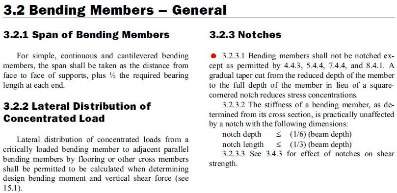
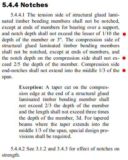
Notches
NDS section 3.2.3, NDS section 5.4.4
At the ends of a glulam, notches on the tension side cannot exceed the lesser of 1/10 of the depth or 3 in.
11.25 in. / 10 = 1.125 in. > 1 in. ✓
At the ends of a glulam, notches on the compression side cannot exceed 2/5 of the depth.
Compression-side notches cannot extend into the middle third of the span.
NDS section 3.4.3
Vmax = wL/2 = 7.556 lb/in. x 14 ft x 12 in./ft / 2 = 634.7 lb
V 'r = (2F'vbdn/3)(dn/d)2 = (2 x 150 psi x 1.5 in. x (11.25 -1 in.)/3) ((11.25-1 in.)/11.25 in.)2 = 1276 lb
1276 lb > 634.7 lb ✓
|
Nominal LRFD Values
Adjusted LRFD Values
Adjusted LRFD Moment and Shear Resistances
Factored Moment and Shear (LRFD) and Actual Deflection
Is Member Adequate? (LRFD) |