Given
Member size unknown for tension chord Load D = 16 psf
Lr = 1 x 1 x 20 psf = 20 psf (AT = 42 ft x 2 ft = 84 sqft < 200 sqft; 7:21 = 4:12; ASCE 7 table 4-1 and section 4.9.1)Stress grade and species No. 2 DF-L Fasteners ignore Adjustment factors CM = 1
Ct = 1
Ci = 1Assume pin-connected truss at 24 in. OC.
Load Combinations
Load Symbol Given Value (psf)
(acting downward)dead load D 16 weight of ice Di 0 earthquake load E 0 load due to fluids F 0 flood loads Fa 0 load due to sub-surface pressure H 0 live load L 0 roof live load Lr 20 rain load R 0 snow load S 0 self-straining force T 0 wind load W 0 wind-on-ice Wi 0
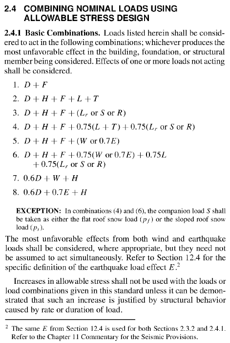
ASCE 7 IBC ASD Load Combination Possible Values (psf) 1 16-8 D + F 16 2 16-9 D + H + F + L + T 16 3 16-10 D + H + F + (Lr or S or R) 36 4 16-11 D + H + F + 0.75(L + T) + 0.75(Lr or S or R) 31 5 16-12 D + H + F + (W or 0.7E) 16 6 16-13 D + H + F + 0.75(W or 0.7E) + 0.75L + 0.75(Lr or S or R) 31 7 16-14 0.6D + W + H --A 8 16-15 0.6D + 0.7E + H --A A Combinations 7 and 8 are not applicable because S is acting in the same direction (downward) as D. See highlighted paragraph in ASCE 7 section C2.4.
(D)max = 16 psf
(D+Lr)max = 36 psf (D+0.75Lr) involves the same load types and is smaller.
Trial Size Based on (D+Lr) Load Combination (ASD)
Load at pins A and C = 36 psf x 5.25 ft x 2 ft = 396 lb (these pass directly into ground connections and do not influence truss)
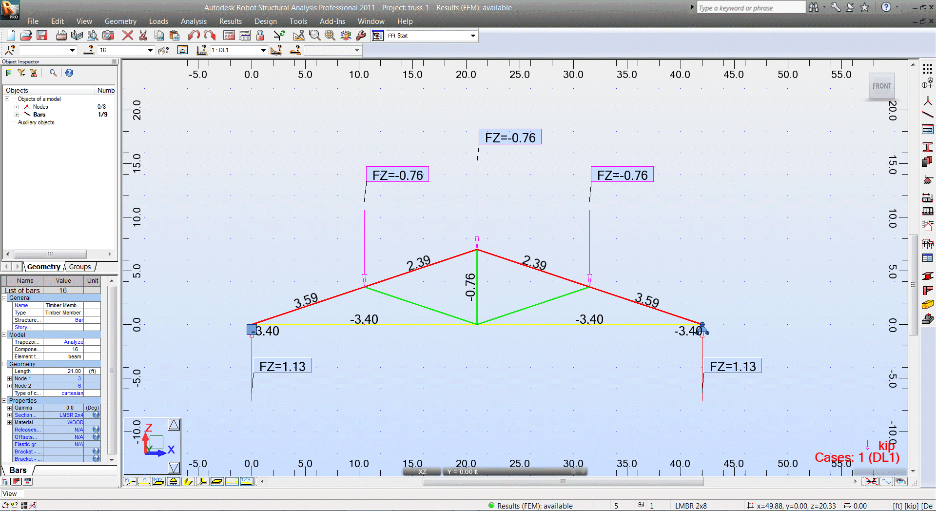
Load at other pins in upper chord = 36 psf x 10.5 ft x 2 ft = 756 lbLoad in bottom chord = 3.4 kip (T) (Autodesk Robot, negative values represent tension)
ft = P/An ≤ F't
Atrial = P/F't = 3400 / (575 psi x 1.25) = 4.73 in.2 (NDS Supplement table 4A, CD = 1.25)
A2x3 = 3.750 in.2 (NDS Supplement table 1B)
A2x4 = 5.250 in.2
Adjusted Design Values
NDS Supplement table 4A Cr = 1.15 if 2"-4" thick members
CM = 1 (given)
CF = 1.5 for Fb, 1.5 for Ft, 1.15 for Fc for both 2x3 and 2x4
Cfu = 1 (not a beam)NDS Supplement section 2.3
CD = 0.9 (D) or 1.25 (D+Lr) depending on load combination
Ct = 1 (given)NDS Supplement section 3.3 CL = 1 (no compression)
NDS Supplement section 3.7
CP = 1 (not a column)
NDS Supplement section 3.10
Cb = 1 (not enough info given)
NDS Supplement section 4.3 Ci = 1 (given)
NDS Supplement section 4.4
CT = 1 (not compression chord)
Property Reference Design
Values (psi)
(Table 4A)Adjustment Factors (Table 4.3.1) Adjusted Design
Values (psi)CD CM Ct CL CF Cfu Cr CP Ci CT Cb bending stress Fb 900 0.9 or 1.25 1 1 1 1.5 1 1.15 1 -- tension stress parallel to grain Ft 575 0.9 or 1.25 1 1 1.5 1 776 or 1078 shear stress parallel to grain Fv 180 0.9 or 1.25 1 1 1 -- compression stress perpendicular to grain Fc⊥ 625 1 1 1 1 -- compression stress parallel to grain Fc 1,350 0.9 or 1.25 1 1 1.15 1 1 -- modulus of elasticity (or MOE) E 1,600,000 1 1 1 -- modulus of elasticity for stability calculations Emin 580,000 1 1 1 1 --
Actual Stress for (D) Load Combination (ASD)
Load at pins A and C = 16 psf x 5.25 ft x 2 ft = 168 lb (these pass directly into ground connections and do not influence truss)
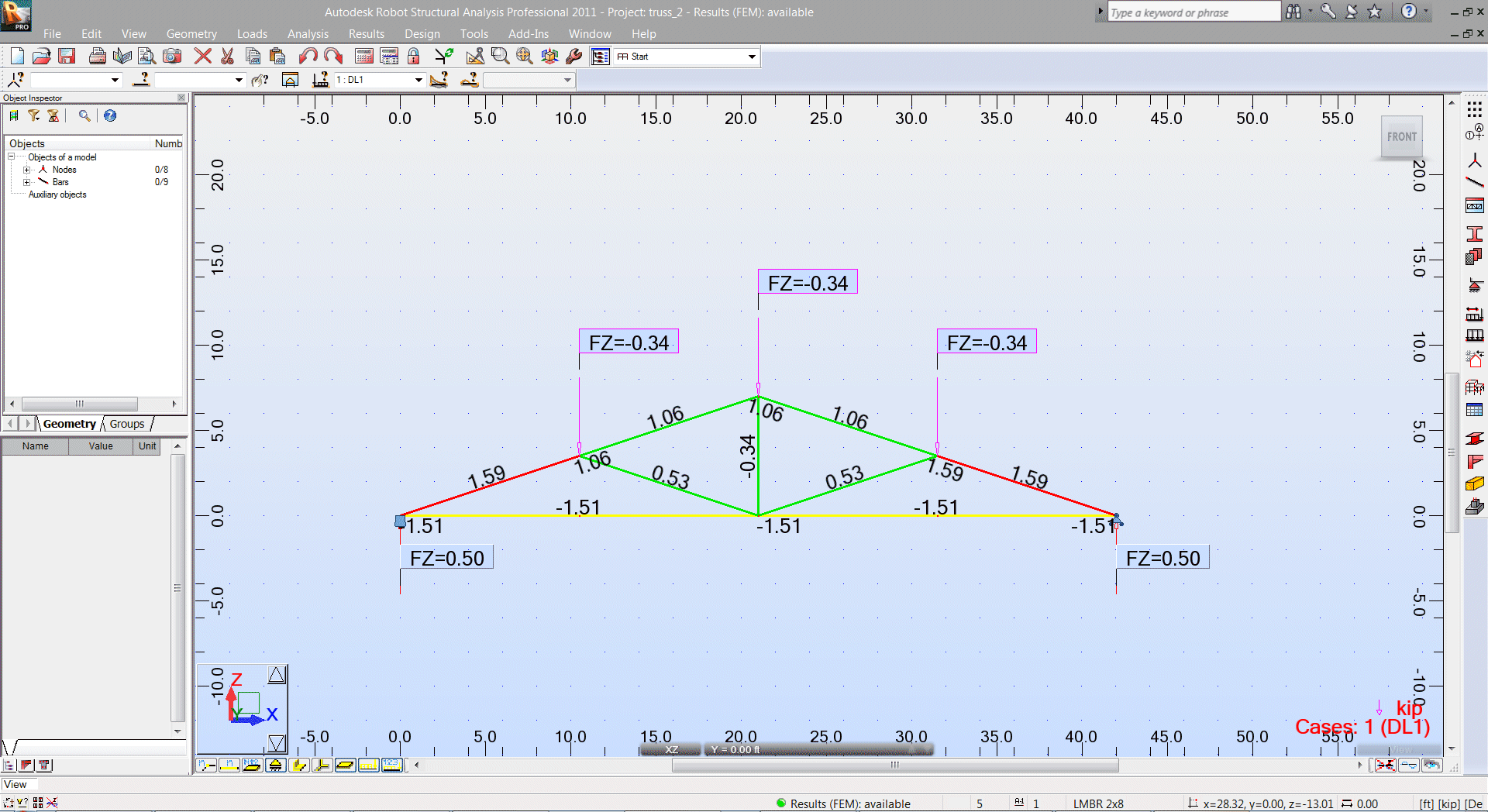
Load at other pins in upper chord = 16 psf x 10.5 ft x 2 ft = 336 lbLoad in bottom chord = 1.51 kip (T) (Autodesk Robot, negative values represent tension)
ft 2x3 = P/An = 1,510 lb / 3.750 in.2 = 403 psi ≤ 776 psi ✓
ft 2x4 = P/An = 1,510 lb / 5.250 in.2 = 288 psi ≤ 776 psi ✓
Actual Stress for (D+Lr) Load Combination (ASD)
Load at pins A and C = 36 psf x 5.25 ft x 2 ft = 396 lb (these pass directly into ground connections and do not influence truss)
Load at other pins in upper chord = 36 psf x 10.5 ft x 2 ft = 756 lbLoad in bottom chord = 3.4 kip (T) (Autodesk Robot, negative values represent tension)
ft 2x3 = P/An = 3,400 lb / 3.750 in.2 = 907 psi ≤ 1078 psi ✓
ft 2x4 = P/An = 3,400 lb / 5.250 in.2 = 648 psi ≤ 1078 psi ✓
∴ A 2x3 or larger would work.