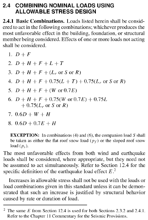
Problem 7.8
Given
Member size 4x10 door header Load D = 120 lb/ft
Lr = 120 lb/ft
W = 8 kip (T)Stress grade and species No. 2 Hem-Fir Fasteners ignore Adjustment factors CM = 1
Ct = 1
Ci = 1Lateral stability is not an issue.
Size (NDS Supplement table 1B)
Ag = 32.38 in.2
An = Ag - 1.5 in. x (XX in. + 1/16 in.) = XX in.2 (NDS section 11.1.2.2 and appendix L table L1)
Sxx = 49.91 in.3
Ixx = 230.8 in.4
Load Combinations
Load Symbol Given Value dead load D 120 lb/ft weight of ice Di 0 earthquake load E 0 load due to fluids F 0 flood loads Fa 0 load due to sub-surface pressure H 0 live load L 0 roof live load Lr 120 lb/ft rain load R 0 snow load S 55 self-straining force T 0 wind load W 8,000 lb wind-on-ice Wi 0
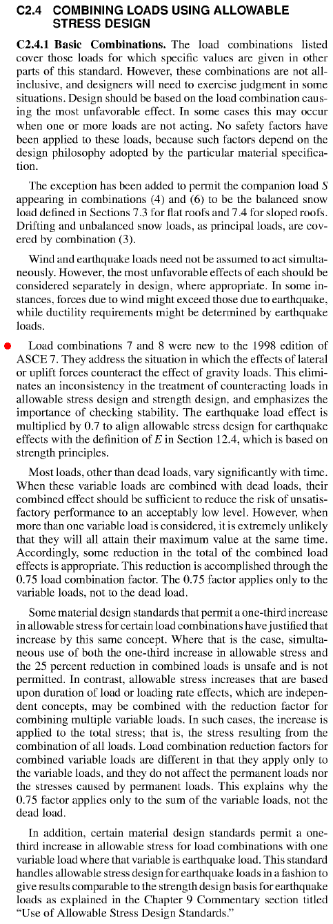
ASCE 7 IBC ASD Load Combination Possible Values 1 16-8 D + F 120 lb/ft 2 16-9 D + H + F + L + T 120 lb/ft 3 16-10 D + H + F + (Lr or S or R) 240 lb/ft 4 16-11 D + H + F + 0.75(L + T) + 0.75(Lr or S or R) 210 lb/ft 5 16-12 D + H + F + (W or 0.7E) 120 lb/ft, 8,000 lb 6 16-13 D + H + F + 0.75(W or 0.7E) + 0.75L + 0.75(Lr or S or R) 210 lb/ft, 6,000 lb 7 16-14 0.6D + W + H --A 8 16-15 0.6D + 0.7E + H --A A Combinations 7 and 8 are not applicable because S is acting in the same direction (downward) as D. See highlighted paragraph in ASCE 7 section C2.4.
(D)max = 120 lb/ft
(D+Lr)max = 240 lb/ft
(D+W)max = 120 lb/ft, 8,000 lb
(D+0.75W+0.75Lr)max = 210 lb/ft, 6,000 lb
Adjusted Design Values
NDS Supplement table 4A Cr = 1 (does not repeat)
CM = 1 (given)
CF = 1.2 for Fb, 1.1 for Ft, 1.0 for Fc
Cfu = 1 (headers are bent around strong axis)NDS Supplement section 2.3
CD = 0.9 (D), 1.25 (D+Lr), 1.6 (D+W), or 1.6 (D+0.75W+0.75Lr) depending on load combination
Ct = 1 (given)NDS Supplement section 3.3 CL = 1 (given)
NDS Supplement section 3.7
CP = 1 (not a column)
NDS Supplement section 3.10
Cb = 1 (not enough info given)
NDS Supplement section 4.3 Ci = 1 (given)
NDS Supplement section 4.4
CT = 1 (not a truss)
Property Reference Design
Values (psi)
(Table 4A)Adjustment Factors (Table 4.3.1) Adjusted Design
Values (psi)CD CM Ct CL CF Cfu Cr CP Ci CT Cb bending stress Fb 850 0.9
1.25
1.61 1 1 1.2 1 1 1 918
1,275
1,632tension stress parallel to grain Ft 525 0.9
1.25
1.61 1 1.1 1 520
722
924shear stress parallel to grain Fv 150 0.9
1.25
1.61 1 1 --
--
--compression stress perpendicular to grain Fc⊥ 405 1 1 1 1 -- compression stress parallel to grain Fc 1,300 0.9
1.25
1.61 1 1 1 1 --
--
--modulus of elasticity (or MOE) E 1,300,000 1 1 1 -- modulus of elasticity for stability calculations Emin 470,000 1 1 1 1 --
Actual Stresses for (D) Load Combination (ASD)
(D)max = 120 lb/ft
Axial tension stress...
ft = P/An = X lb / 32.38 in.2 = X psi ≤ 520 psi
Bending stress...
wD = 120 lb/ft
Vmax = 120 lb/ft x 12 ft / 2 = 720 lb
Mmax = 0.5 x 6 ft x 720 lb = 2,160 lb-ft x 12 in./ft = 25,920 lb-in.fb = M/S = 25,920 lb-in. / 49.91 in.3 = 519 psi ≤ 918 psi ✓
Check formulas in NDS section 3.9.1 for combined axial tension and bending...
ft/F't + fb/F*b = X/520 + 519/918 = X ≤ 1.0
(fb-ft)/F**b = (519-X)/918 = X ≤ 1.0Severity...
519 / 918 = 0.565
Actual Stresses for (D+Lr) Load Combination (ASD)
(D+Lr)max = 240 lb/ft
Axial tension stress...
ft = P/An = X lb / 32.38 in.2 = X psi ≤ 722 psi
Bending stress...
wD+Lr = 240 lb/ft
Vmax = 240 lb/ft x 12 ft / 2 = 1,440 lb
Mmax = 0.5 x 6 ft x 1,440 lb = 4,320 lb-ft x 12 in./ft = 51,840 lb-in.fb = M/S = 51,840 lb-in. / 49.91 in.3 = 1,039 psi ≤ 1,275 psi ✓
Check formulas in NDS section 3.9.1 for combined axial tension and bending...
ft/F't + fb/F*b = X/722 + 1,039/1,275 = X ≤ 1.0
(fb-ft)/F**b = (1,039-X)/1,275 = X ≤ 1.0Severity...
1,039 / 1,275 = 0.815
Actual Stresses for (D+W) Load Combination (ASD)
(D+W)max = 120 lb/ft, 8000 lb
Axial tension stress...
ft = P/An = 8,000 lb / 32.38 in.2 = 247 psi ≤ 924 psi ✓
Bending stress...
wD = 1 20 lb/ft
Vmax = 1 20 lb/ft x 12 ft / 2 = 720 lb
Mmax = 0.5 x 6 ft x 720 lb = 2,160 lb-ft x 12 in./ft = 25,920 lb-in.fb = M/S = 25,920 lb-in. / 49.91 in.3 = 519 psi ≤ 1,632 psi ✓
Check formulas in NDS section 3.9.1 for combined axial tension and bending...
ft/F't + fb/F*b = 247/924 + 519/1,632 = 0.585 ≤ 1.0 ✓
(fb-ft)/F**b = (519-247)/1,632 = 0.167 ≤ 1.0 ✓Severity...
247 / 924 = 0.267
519 / 1,632 = 0.318
Actual Stresses for (D+W) Load Combination (ASD)
(D+0.75W+0.75Lr)max = 210 lb/ft, 6,000 lb
Axial tension stress...
ft = P/An = 6,000 lb / 32.38 in.2 = 186 psi ≤ 924 psi ✓
Bending stress...
wD = 210 lb/ft
Vmax = 210 lb/ft x 12 ft / 2 = 1,260 lb
Mmax = 0.5 x 6 ft x 1,260 lb = 3,780 lb-ft x 12 in./ft = 45,360 lb-in.fb = M/S = 45,360 lb-in. / 49.91 in.3 = 909 psi ≤ 1,632 psi ✓
Check formulas in NDS section 3.9.1 for combined axial tension and bending...
ft/F't + fb/F*b = 186/924 + 909/1,632 = 0.758 ≤ 1.0 ✓
(fb-ft)/F**b = (909-186)/1,632 = 0.443 ≤ 1.0 ✓Severity...
186 / 924 = 0.298
909 / 1,632 = 0.557
∴ The 4x10 is okay for all load combinations. The D+Lr combination is the most severe (0.815).