Given
Member size 2x10 top chord Load D = 20 psf (borrowed from problem 7.3)
S = 55 psfStress grade and species No. 2 Him-Fir Unbraced length lu = 0 for weak axis (sheathing)
lu = for strong axisFasteners ignore Adjustment factors CM = 1
Ct = 1
Ci = 1Assume pin-connected truss at 4 ft OC (borrowed from problem 7.3).
Size (NDS Supplement table 1B)
A = 13.88 in.2
Sxx = 21.39 in.3
Syy = 3.469 in.3
Ixx = 98.93 in.4
Iyy = 2.602 in.4
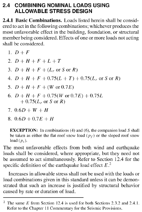
Load Combinations
Load Symbol Given Value (psf)
(acting downward)dead load D 20 weight of ice Di 0 earthquake load E 0 load due to fluids F 0 flood loads Fa 0 load due to sub-surface pressure H 0 live load L 0 roof live load Lr 0 rain load R 0 snow load S 55 self-straining force T 0 wind load W 0 wind-on-ice Wi 0
ASCE 7 IBC ASD Load Combination Possible Values (psf) 1 16-8 D + F 20 2 16-9 D + H + F + L + T 20 3 16-10 D + H + F + (Lr or S or R) 75 4 16-11 D + H + F + 0.75(L + T) + 0.75(Lr or S or R) 61.25 5 16-12 D + H + F + (W or 0.7E) 20 6 16-13 D + H + F + 0.75(W or 0.7E) + 0.75L + 0.75(Lr or S or R) 61.25 7 16-14 0.6D + W + H -- 8 16-15 0.6D + 0.7E + H -- (D)max = 20 psf
(D+S)max = 75 psf
Adjusted Design Values
NDS Supplement table 4A Cr = 1 (move than 24 in. OC)
CM = 1 (given)
CF = 1.1 for Fb, 1.1 for Ft, 1 for Fc
Cfu = 1NDS Supplement section 2.3
NDS Supplement section 3.3CD = 0.9 (D) or 1.15 (S)
Ct = 1 (given)CL = 1 (sheathing on compression side; assume ends at points of bearing have lateral support to prevent rotation)
NDS Supplement section 3.7
Ke = 1 (assumed)
le = Ke l = sqrt[(60 in.)2 + (60 in. x 5/12)2] = 65 in.
le1/d1 = 65 in. / 9.25 in. = 7.027 (strong)
le2/d2 = Ke lu2 / 1.5 in. = 0 / 1.5 in. = 0 (weak)
le1/d1 > le2/d2 (strong axis governs)
FcE = 0.822 E'min / (le/d)2 = 7,824 psi
F*c = F'c without CP = 1,170 (D) or 1,495 (S) psi
c = 0.8
CP = (1+FcE/F*c)/2c - sqrt{[(1+FcE/F*c) / 2c]2 - (FcE/F*c)/c}
= 0.9673 (D) or 0.9572 (S)NDS Supplement section 3.10
NDS Supplement section 4.3Cb = 1 (not enough info given)
Ci = 1 (given)
NDS Supplement section 4.4
CT = 1 (larger than 2x4)
Property Reference Design
Values (psi)
(Table 4A)Adjustment Factors (Table 4.3.1) Adjusted Design
Values (psi)CD CM Ct CL CF Cfu Cr CP Ci CT Cb bending stress Fb 850 0.9
1.151 1 1 1.1 1 1 1 841.5
1,075tension stress parallel to grain Ft 525 0.9
1.151 1 1.1 1 -- shear stress parallel to grain Fv 150 0.9
1.151 1 1 -- compression stress perpendicular to grain Fc⊥ 405 1 1 1 1 -- compression stress parallel to grain Fc 1,300 0.9
1.151 1 1 0.9673
0.95721 1,132
1,431modulus of elasticity (or MOE) E 1,300,000 1 1 1 -- modulus of elasticity for stability calculations Emin 470,000 1 1 1 1 470,000
Actual Stress for (D) Load Combination (ASD)
Check compression stress...
Load at pins A and C = 20 psf x 2.5 ft x 4 ft = 200 lb (these pass directly into ground connections and do not influence truss)
Load at other pins in upper chord = 20 psf x 5 ft x 4 ft = 400 lbHeight of truss peak = 10 ft x 5/12 = 4.167 ft (needed for drawing truss)
Height of intermediate nodes = 5 ft x 5/12 = 2.083 ft (estimated from given diagram)Load in top chord = 1.56 kip (C) (Autodesk Robot, positive values represent compression)
fc = P/A = 1,560 lb / 13.88 in.2 = 112.4 psi ≤ 1,132 psi ✓
It is conservative to consider bending alone in the top chord members...
wD = 20 psf x 4 ft = 80 lb/ft
Vmax = 80 lb/ft x 5 ft / 2 = 200 lb
Mmax = 0.5 x 2.5 ft x 200 lb = 250 lb-ft x 12 in./ft = 3,000 lb-in.fb = M/S = 3,000 lb-in. / 21.39 in.3 = 140.3 psi ≤ 841.5 psi ✓
Check formula in NDS section 3.9.2 for combined axial compression and bending...
(fc/F'c)2 + fb1/{F'b1[1-(fc/FcE1)]} + fb2/{F'b2[1-(fc/FcE2)-(fb1/FbE)2]} ≤ 1.0
(112.4/1,132)2 + 140.3/{841.5[1-(112.4/7,824)]} + 0 = 0.4875 ≤ 1.0 ✓
Actual Stress for (D+S) Load Combination (ASD)
Check compression stress...
Load at pins A and C = 75 psf x 2.5 ft x 4 ft + 5 psf x 5 ft x 4 ft = 850 lb (these pass directly into ground connections and do not influence truss)
Load at other pins in upper chord = 75 psf x 5 ft x 4 ft = 1,500 lbLoad in top chord = 3.90 kip (C) (Autodesk Robot, positive values represent compression)
fc = P/A = 5,850 lb / 13.88 in.2 = 421.5 psi ≤ 1,431 psi ✓
It is conservative to consider bending alone in the top chord members...
wD = 75 psf x 4 ft = 300 lb/ft
Vmax = 300 lb/ft x 5 ft / 2 = 750 lb
Mmax = 0.5 x 2.5 ft x 750 lb = 937.5 lb-ft x 12 in./ft = 11,250 lb-in.fb = M/S = 11,250 lb-in. / 21.39 in.3 = 525.9 psi ≤ 1,075 psi ✓
Check formula in NDS section 3.9.2 for combined axial compression and bending...
(fc/F'c)2 + fb1/{F'b1[1-(fc/FcE1)]} + fb2/{F'b2[1-(fc/FcE2)-(fb1/FbE)2]} ≤ 1.0
(421.5/1,431)2 + 525.9/{1,075[1-(421.5/7,824)]} + 0 = 0.6038 ≤ 1.0 ✓