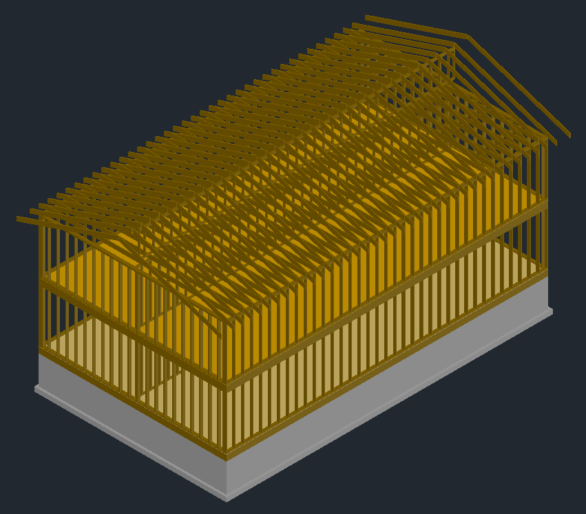
You will probably need to at least create some 2D drawings this semester. You may even want to create some 3D drawings. The following shows one way to create 3D drawings from 2D drawings in AutoCAD. You are welcome to open the corresponding files as you follow along: all_drawings.dwg, 3d_model.dwg, construction_sequence.dwg (these should open in AutoCAD 2010 and later). Here is what the finished model looks like.
| As you can see here, I like to spread the various drawings about the modeling space. | 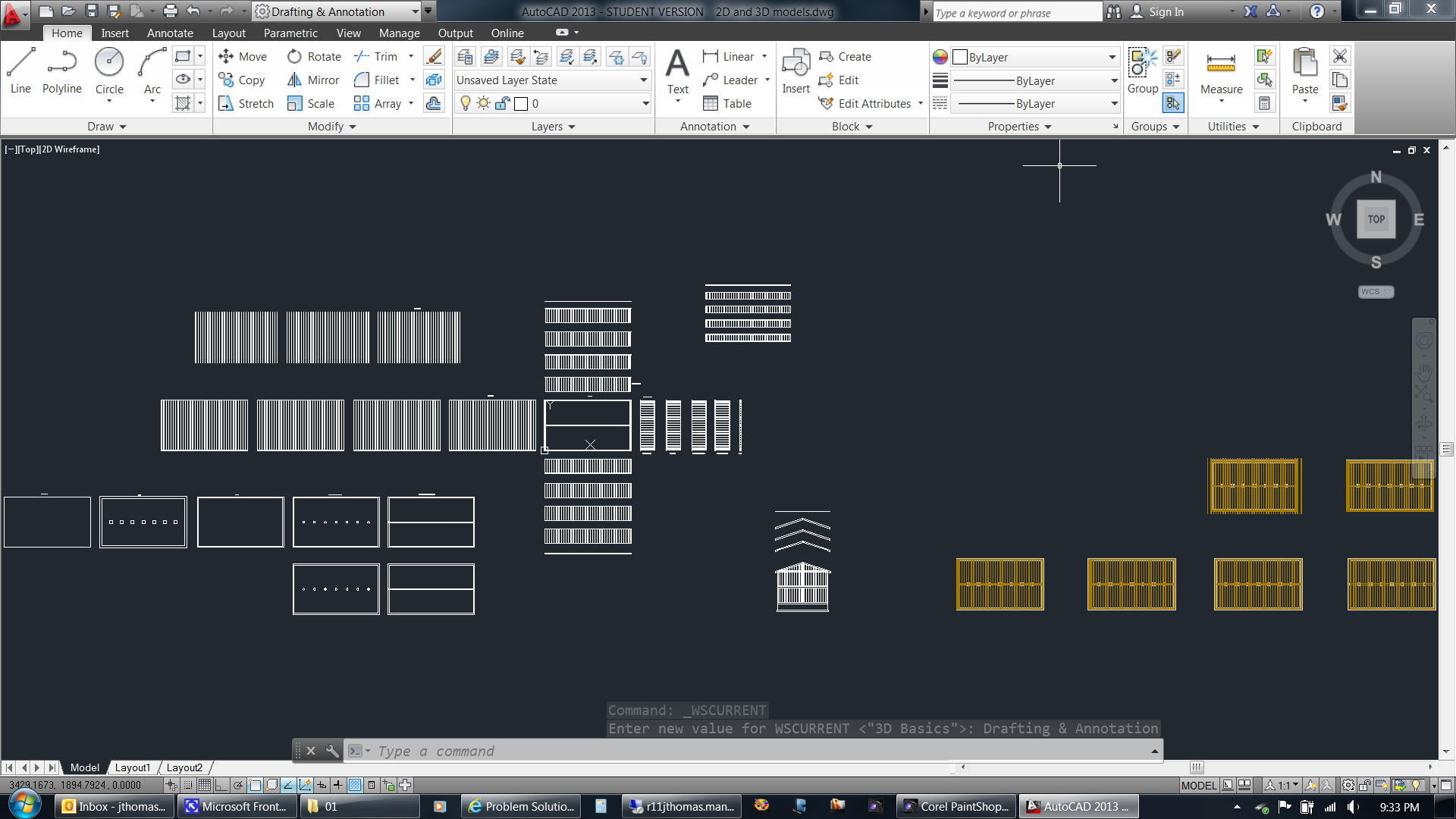 |
|
| I begin by drawing a top (plan) view of the first floor. I draw everything in inches (1 drawing unit = 1 inch). | 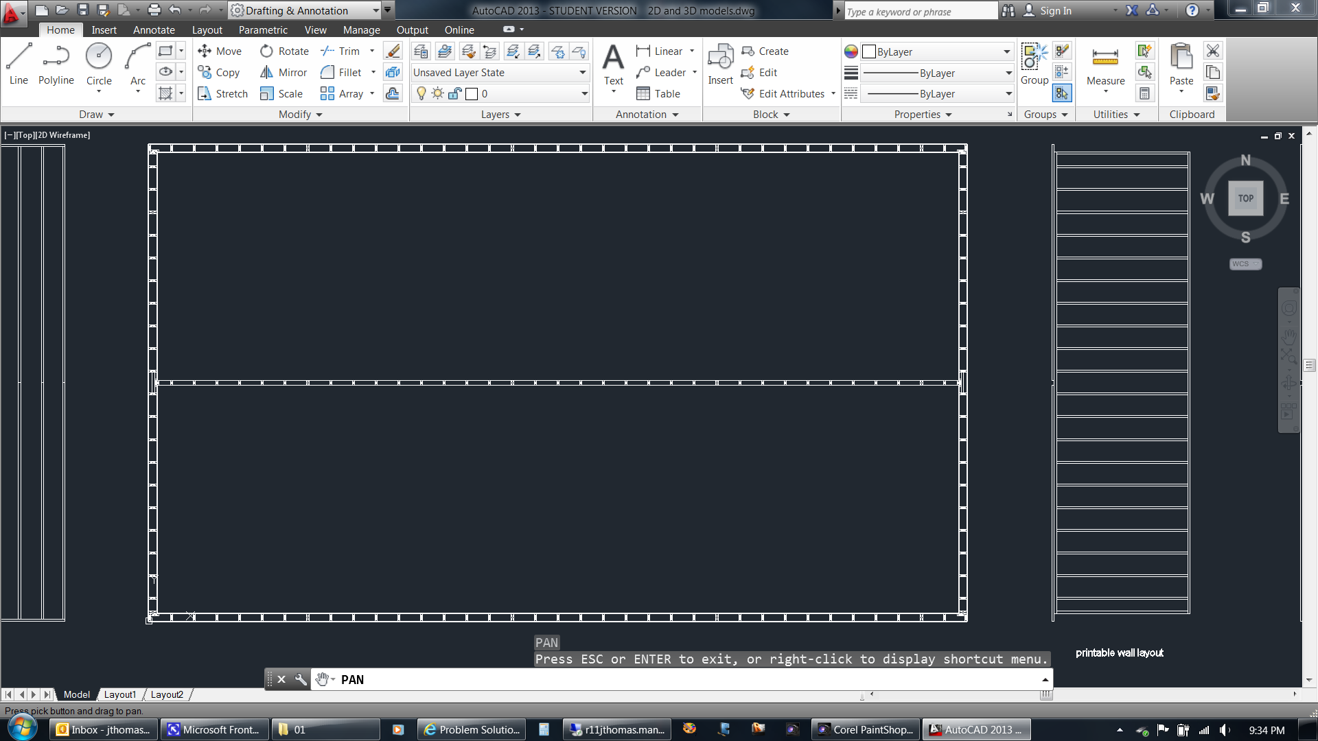 |
|
| I include the studs, and sometimes the plywood and drywall, in order to help me think through the details. | 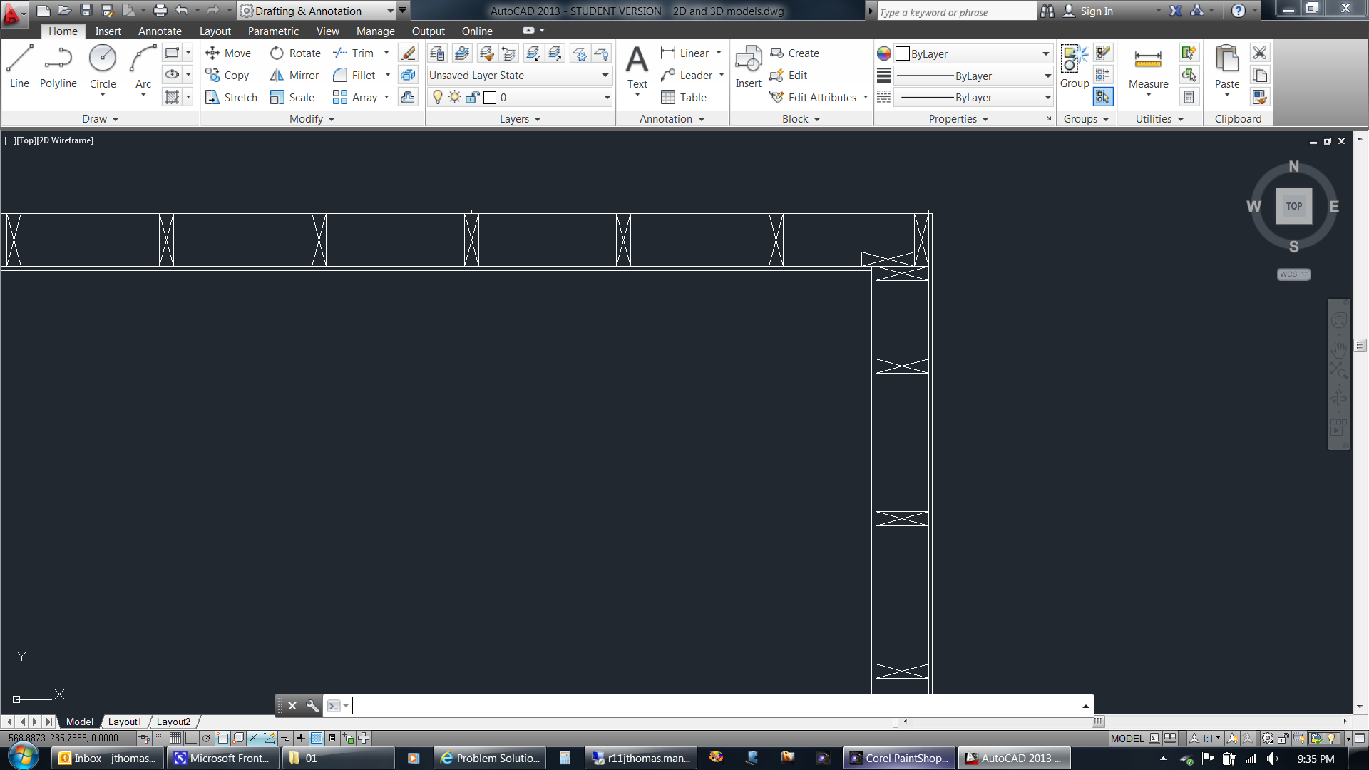 |
|
| I use offset lines (from the top view) for the top and bottom plates of the first exterior wall. I extend the stud lines from the top view and then trim the portion of those lines that is between the top view and the wall. | 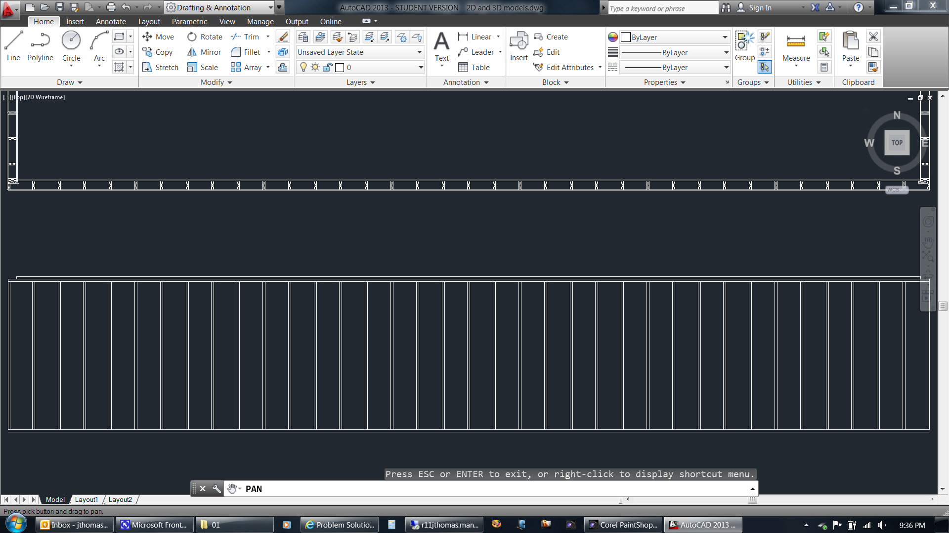 |
|
| I do the same thing for the interior walls... | 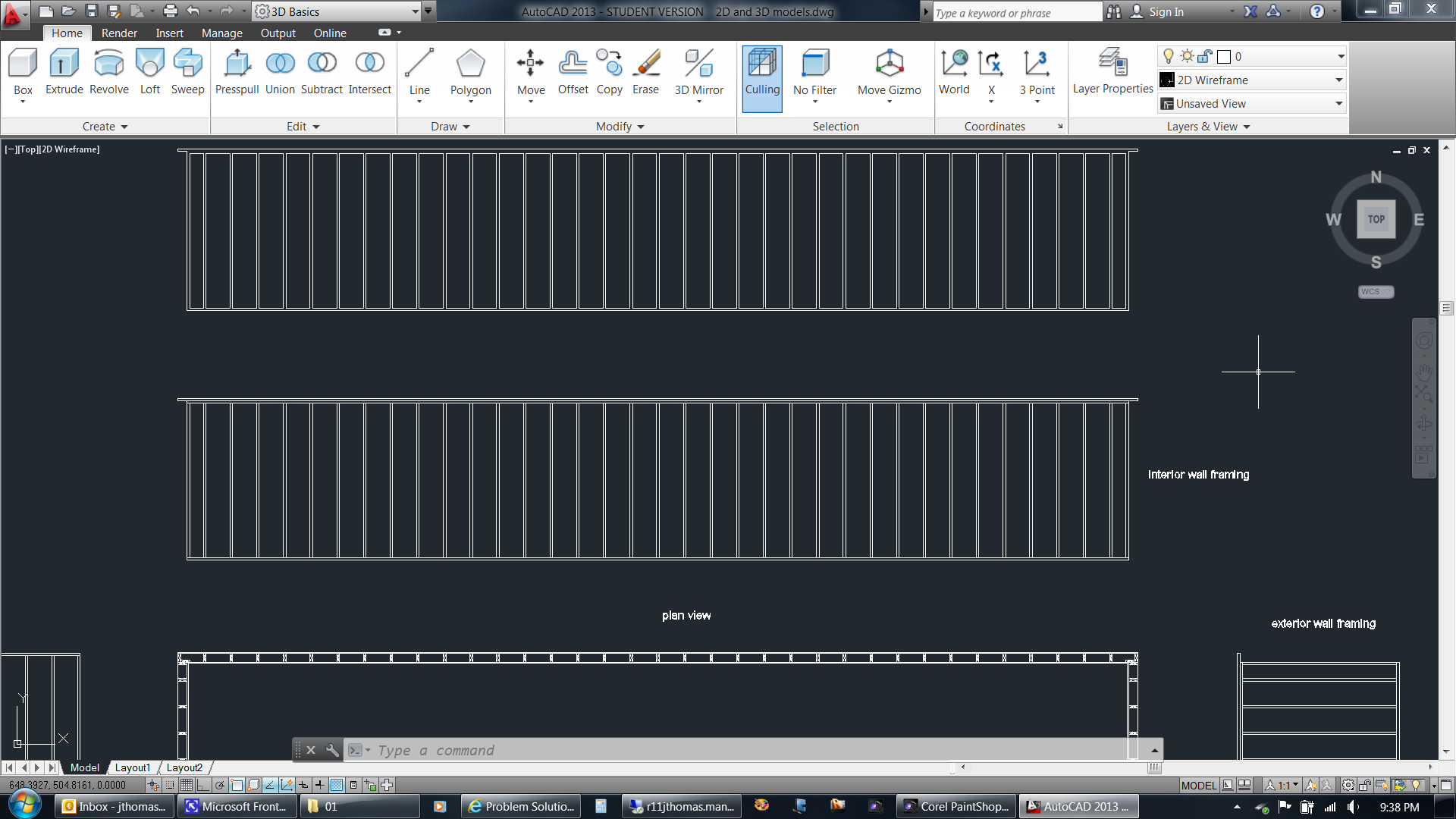 |
|
| ...and the floor framing. If desired I can add dimensions and print the various 2D drawings at this point. | 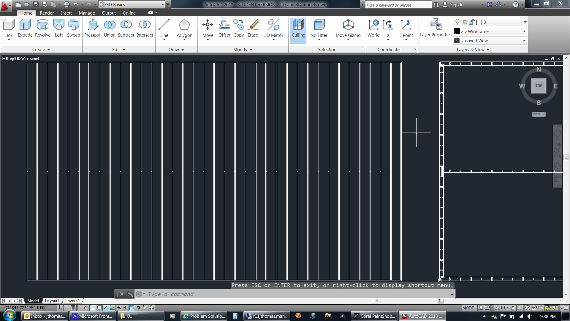 |
|
| I can also convert the 2D drawings to solid models. Here you can see the top view to the left. Next to that is one of the exterior walls. To the right of that is just an outline of that exterior wall. To the right of that is a copy where the lines have been joined into polylines (you can't see any difference in the screen capture). In the next drawing I extruded the polylines and then subtracted the interior extrusions from the outermost extrusion (again, you can't see any difference). This creates a wall with hollow spots between the studs. Lastly, I created a copy of the solid wall and rotate it into a vertical position. | 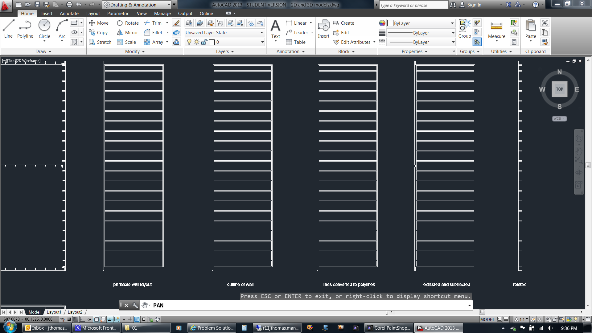 |
|
| Here I have switched to the 3D Basics workspace and am changing from the 2D wireframe visual style to the realistic visual style. | 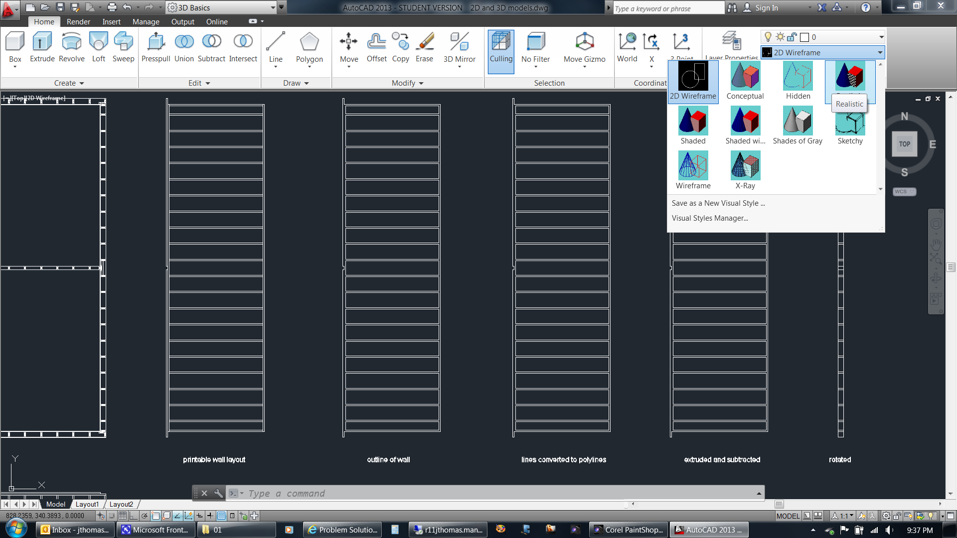 |
|
| The solid walls now appear solid, while the 2D drawings still look the same. | 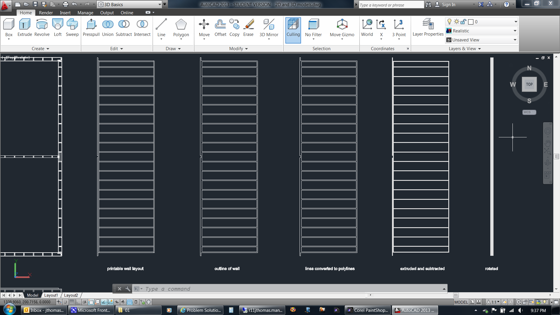 |
|
| Here's what the sequence of wall modifications looks like in the Home (isometric) view. You can see the difference between the polylines and the extruded polylines. | 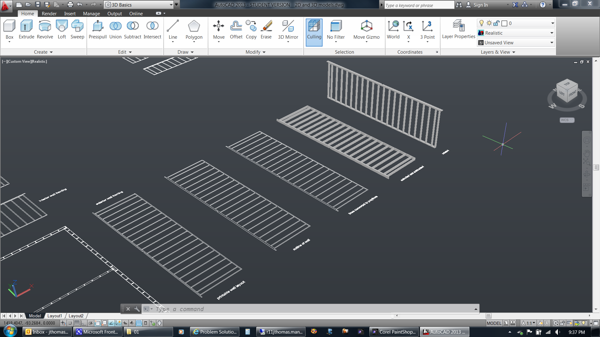 |
|
| Here are all the components done the same way (2D converted to 3D)... | 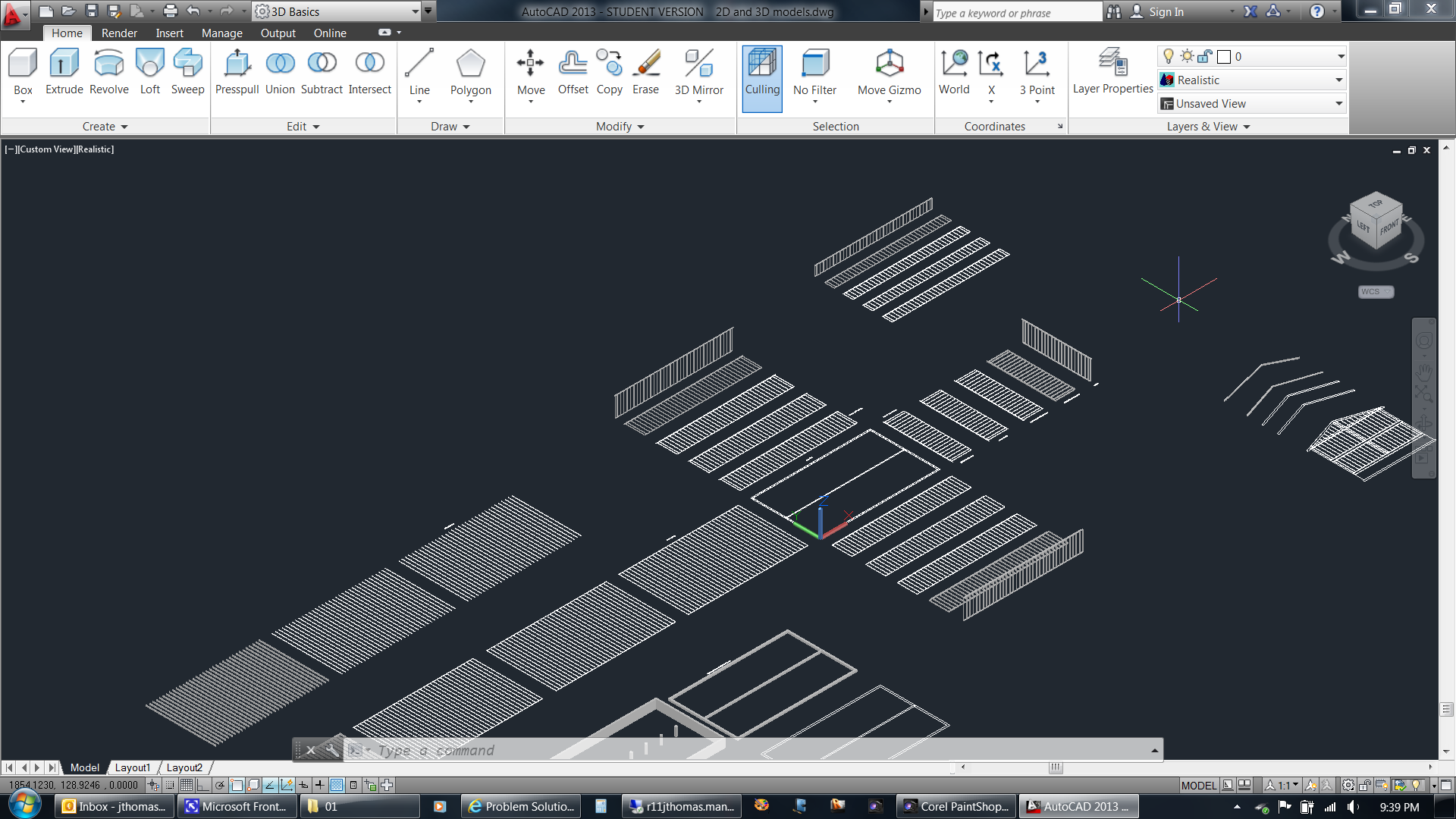 |
|
| ...including the foundation. | 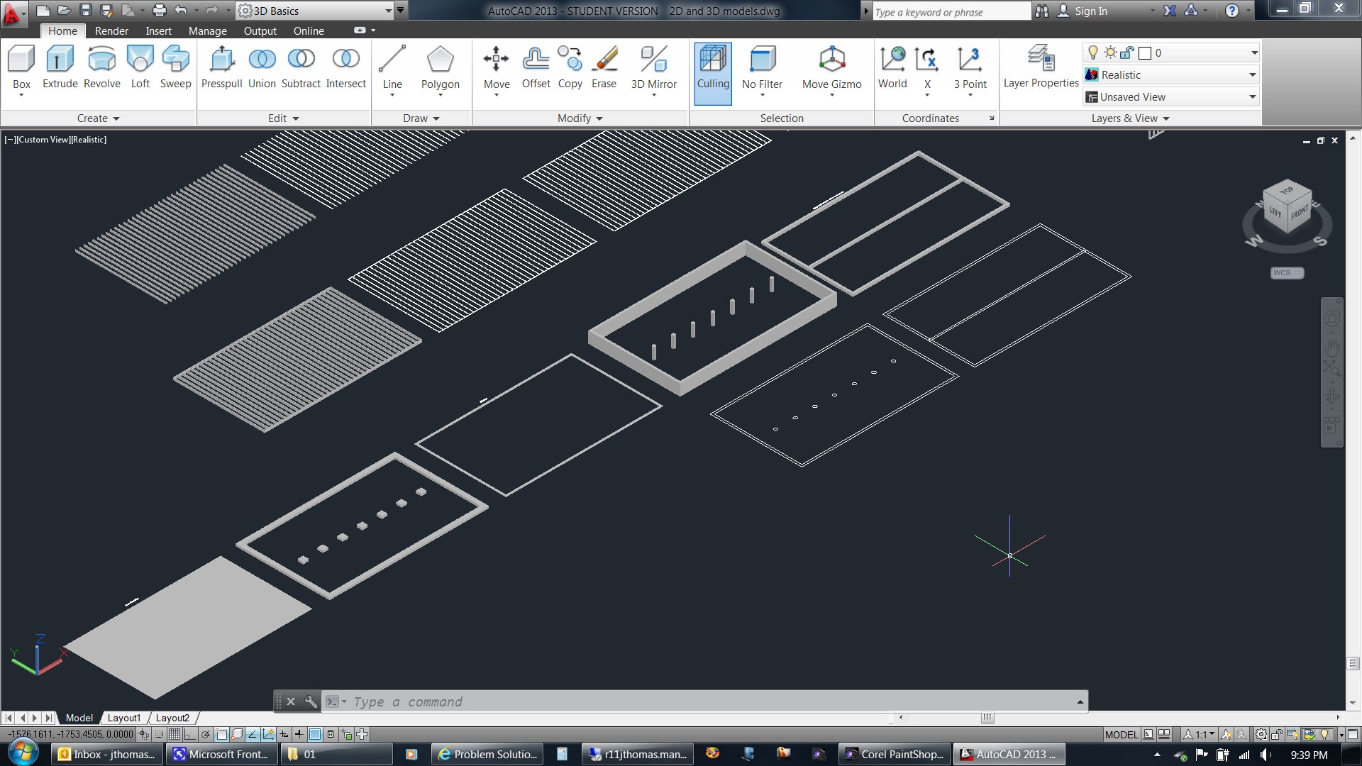 |
|
| To help visualize the rafters, I like to draw a full side view of the building. | 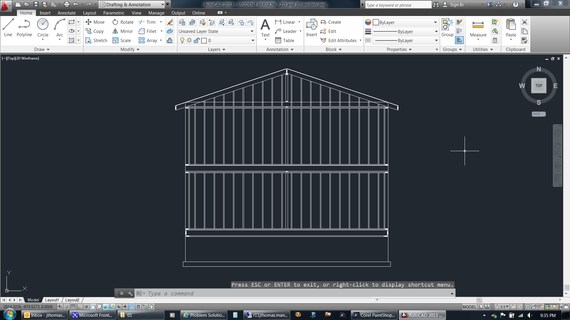 |
|
| Once I'm happy with the rafter size and orientation, I copy and extrude a pair of rafters. I then assign the various solid components to different layers, set a color for each layer, and begin assembling. | 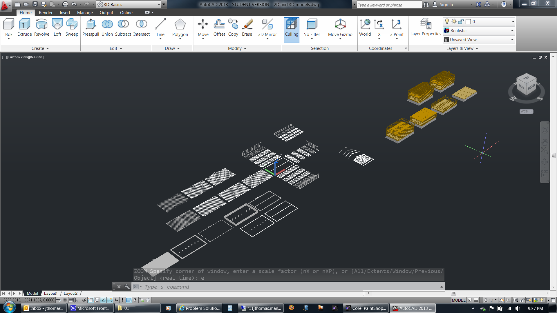 |
|
| Here is a closer view of the assembly sequence. I copy and paste as I go. This saves time if (when) I later realize I've made a mistake. I can erase just the steps after that point instead of starting from the very beginning. | 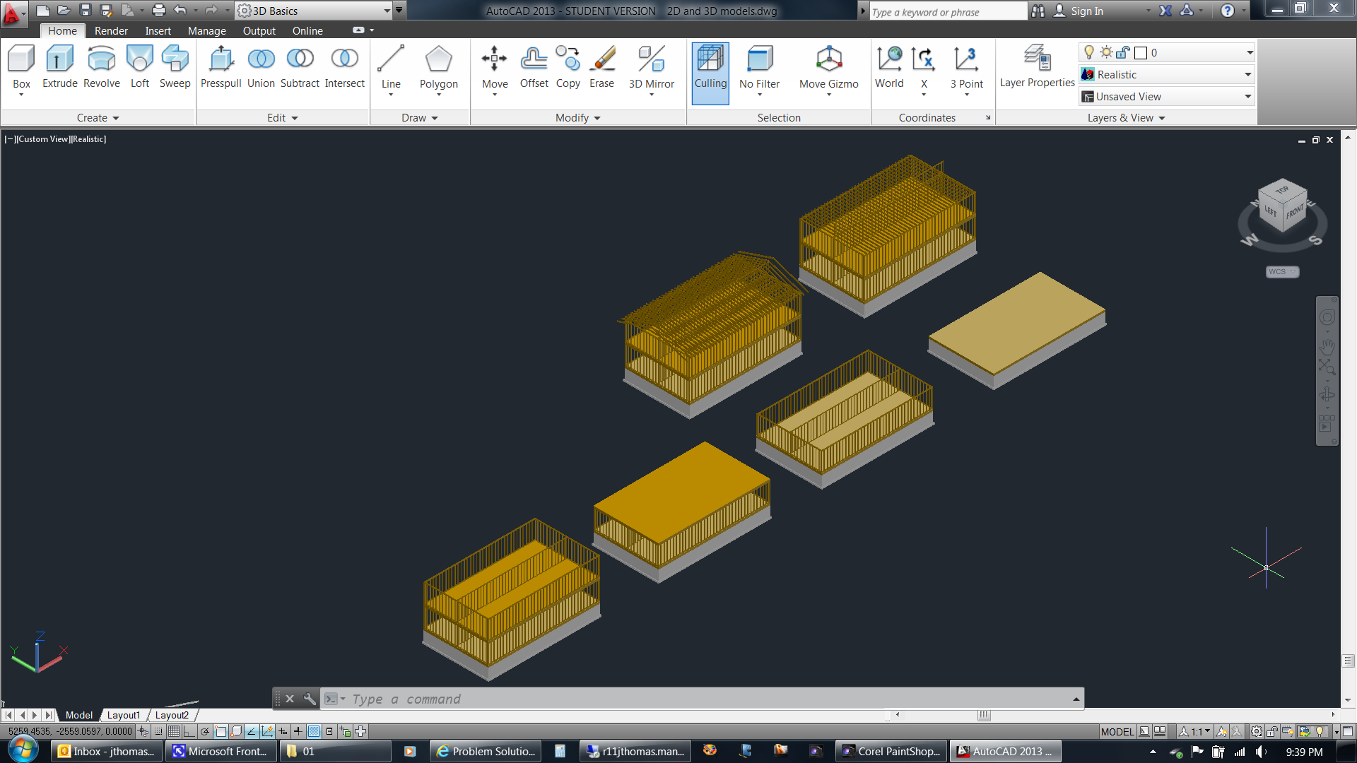 |
|
| Once all of the components have been copied and moved into position, I can then use the model for various things. | 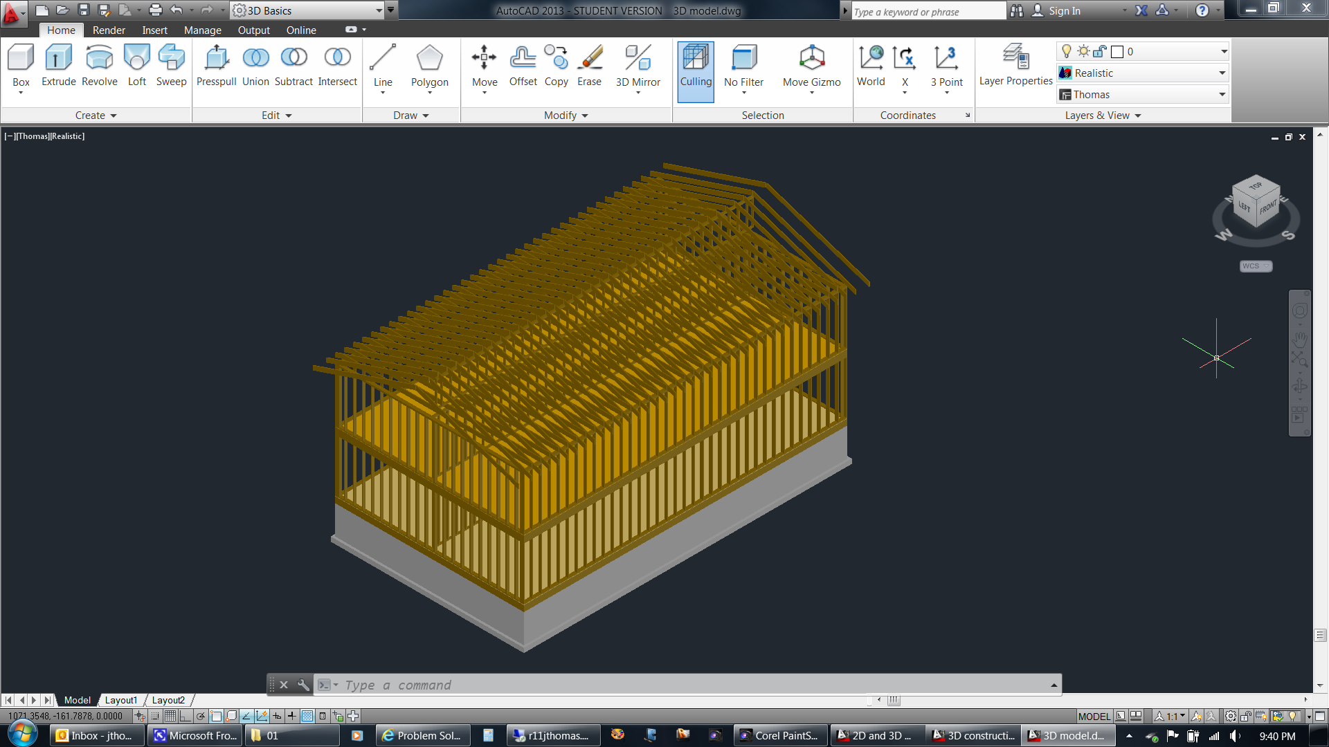 |
|
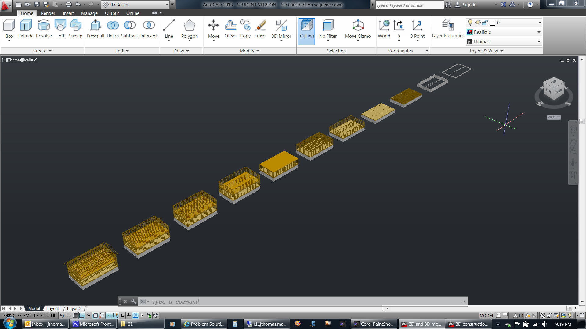
As an example, here the model has been used to illustrate a simple
construction sequence.
|
 |