Experimental
Procedures
- Be sure to write down all of the dimension measurements
for the beam you are using. In the sample results, the stainless steel
half was on the top and the aluminum half was on the
bottom. This may be reversed if you desire.
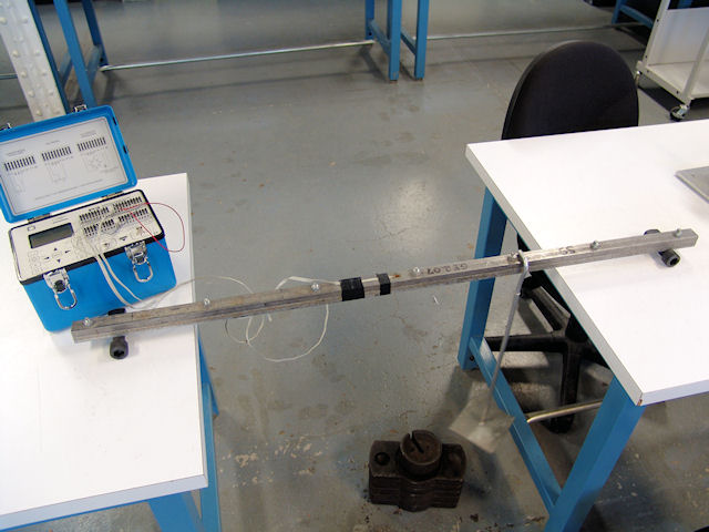
- Set up the strain indicators just as in previous experiments (quarter-bridge circuit).
This time we will
use two axial strain gages, one on the top surface and
one on the bottom surface of the beam. The gage factors
may not be the same for both strain gages.
- The axial strain on the top surface will decrease with
increasing load because the top of the beam is in pure
compression, and the axial strain on the bottom surface
will increase with increasing load because the bottom of
the beam is in pure tension.
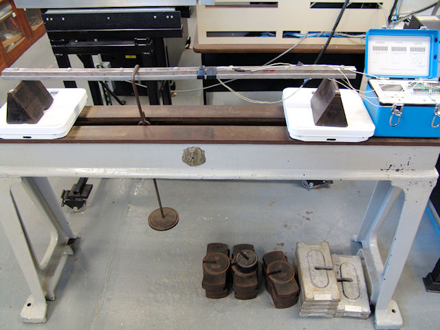
If using dead weights

- Place the weight hanger on the beam (making sure it does not touch the
lathe bed), and zero the strain indicators.
- Take strain measurements for 10 loads in 10 lb increments up to 100 lb.
If using the TO universal testing machine
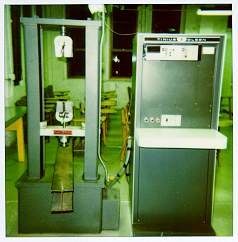
- Place a piece of bar stock between the beam and
the load head.
- Zero the strain indicators and the load readout
while the load head is not in contact with the
bar stock.
- Set the load range to 600 lb.
- Always keep the load-head speed on slow.
- Press the "Lower" button to lower the
load head and apply the load. You can raise the
load head to decrease the load if needed.
- The load knob has a dead spot, so it is hard to
stop the load on even increments.
- Take strain measurements for 10 loads in
approximately 10 lb increments up to 100 lb.