The WIMP51
The WIMP51 is a simplified model
of the 8051 microcontroller used as an aide to introduce concepts of processor
architecture and as a basis to form hardware-software systems from the most
basic level (from the ground up). It
supports 13 of the 8051’s 111 instructions.
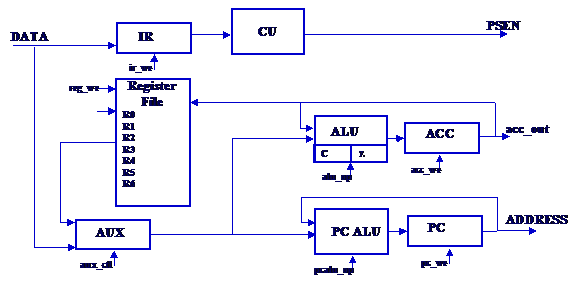
Its simple architecture (shown above) makes it easy for students to
understand. Each instruction is
machine-code and functionally compatible with instructions of the standard
8051, allowing students to use standard compilers to generate and simulate
machine code. The WIMP51 was constructed
as a fully synthesizable VHDL model, allowing hardware-software co-simulation
using VHDL simulation tools as well as implementation and testing in hardware
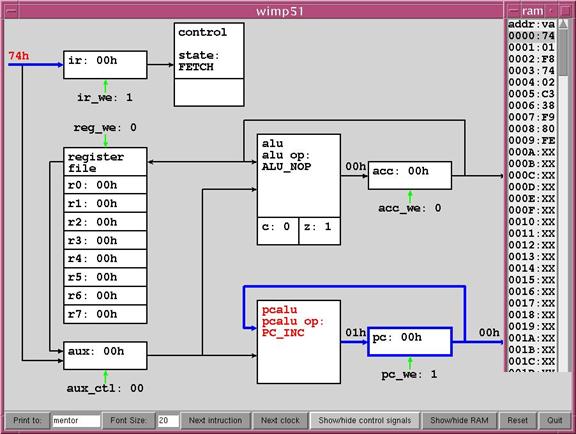
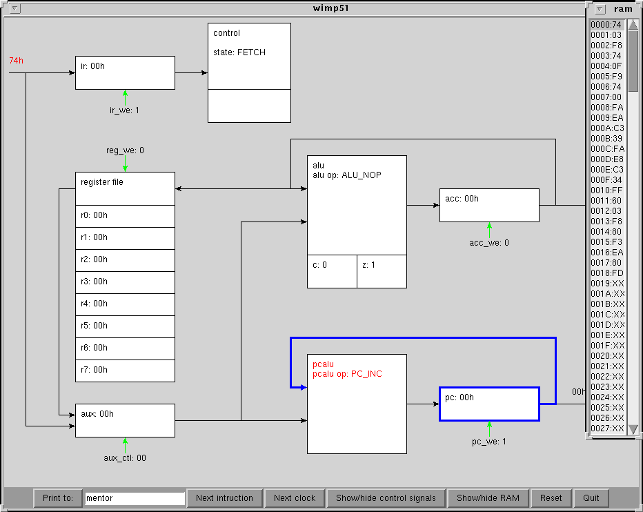
using an FPGA. To further aid understanding
of how the processor works, an animated visualization tool for the WIMP was
created in Tcl/Tk to work along with Mentor Graphics ModelSim simulation tools
(See below). The animated tool allows the student to step through his code one
instruction or one clock cycle at a time and see how data moves through the
processor and the state of individual control lines. Additional details about the WIMP51 can be
found in the VHDL model code and documentation, in a
set of introductory
slides, in our laboratories, or in associated publications, including:
§
D. Sullins, Design
of an 8051 Compatible Processor and Simulator for use in Undergraduate
Coursework, Masters thesis,
§
D. Sullins, H.
Pottinger, D. Beetner, "The WIMP51: A Simple Processor and Visualization
Tool to Introduce Undergraduates to Computer Organization," Computers
in Education Journal, vol. 13, pp
17-23, Jan. 2003.
§
D. Sullins, D.
Beetner, H. Pottinger, "Development of a Simple Processor and Simulator for
Use in Undergraduate Coursework," Proceedings of the 4th European
Workshop on Microelectronics Education - EWME 2002.
§
D. Sullins and H.
Pottinger, "Animation of a VHDL Model in Modelsim Using Tcl/Tk," Proceedings
of the 18th Annual Mentor Graphics Users Group,
CLICK HERE TO SEE AN ANIMATION OF
THE WIMP51 IN ACTION
(animated gif file size approximately 750k)
Figure
1. The Visual Wimp shows the contents of each register, the contents of code
memory, the current active address in memory, the active datalines within the
WIMP, the state of each control signal, and the operation currently being
performed by each logic block. Students
may step through the code one instruction at a time or one clock cycle at a
time.